How to Use UV LED: Examples, Pinouts, and Specs
Introduction
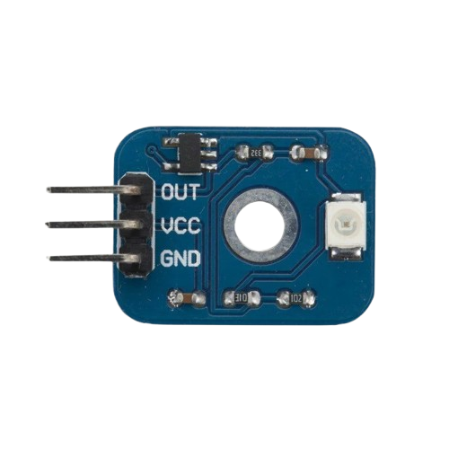
The GOJJU 7017 UV LED is a high-performance ultraviolet light-emitting diode designed for applications requiring precise and efficient UV light emission. This component emits light in the ultraviolet spectrum, making it ideal for sterilization, curing of inks and adhesives, counterfeit detection, and various scientific and industrial applications. Its compact size and robust design ensure reliable performance in demanding environments.
Explore Projects Built with UV LED

Explore Projects Built with UV LED
Technical Specifications
The following table outlines the key technical specifications of the GOJJU 7017 UV LED:
| Parameter | Value |
|---|---|
| Manufacturer | GOJJU |
| Part ID | 7017 |
| Wavelength Range | 365 nm - 400 nm (UV-A range) |
| Forward Voltage (Vf) | 3.0V - 3.6V |
| Forward Current (If) | 20 mA (typical) |
| Power Dissipation | 120 mW (maximum) |
| Viewing Angle | 120° |
| Operating Temperature | -30°C to +85°C |
| Storage Temperature | -40°C to +100°C |
| Package Type | 5mm round |
Pin Configuration and Descriptions
The GOJJU 7017 UV LED has two pins, as described in the table below:
| Pin | Name | Description |
|---|---|---|
| 1 | Anode (+) | Connect to the positive terminal of the power supply |
| 2 | Cathode (-) | Connect to the negative terminal of the power supply |
Usage Instructions
How to Use the UV LED in a Circuit
- Power Supply: Ensure the power supply provides a forward voltage between 3.0V and 3.6V. Use a current-limiting resistor to prevent overcurrent damage.
- Resistor Calculation: To calculate the resistor value, use Ohm's Law:
[ R = \frac{V_{supply} - V_f}{I_f} ]
For example, if the supply voltage is 5V and the forward voltage is 3.3V with a forward current of 20 mA:
[ R = \frac{5V - 3.3V}{0.02A} = 85 , \Omega ]
Use the nearest standard resistor value (e.g., 82Ω or 100Ω). - Polarity: Connect the anode (+) to the positive terminal of the power supply and the cathode (-) to the negative terminal.
- Heat Management: If the LED operates for extended periods, ensure proper heat dissipation to maintain performance and longevity.
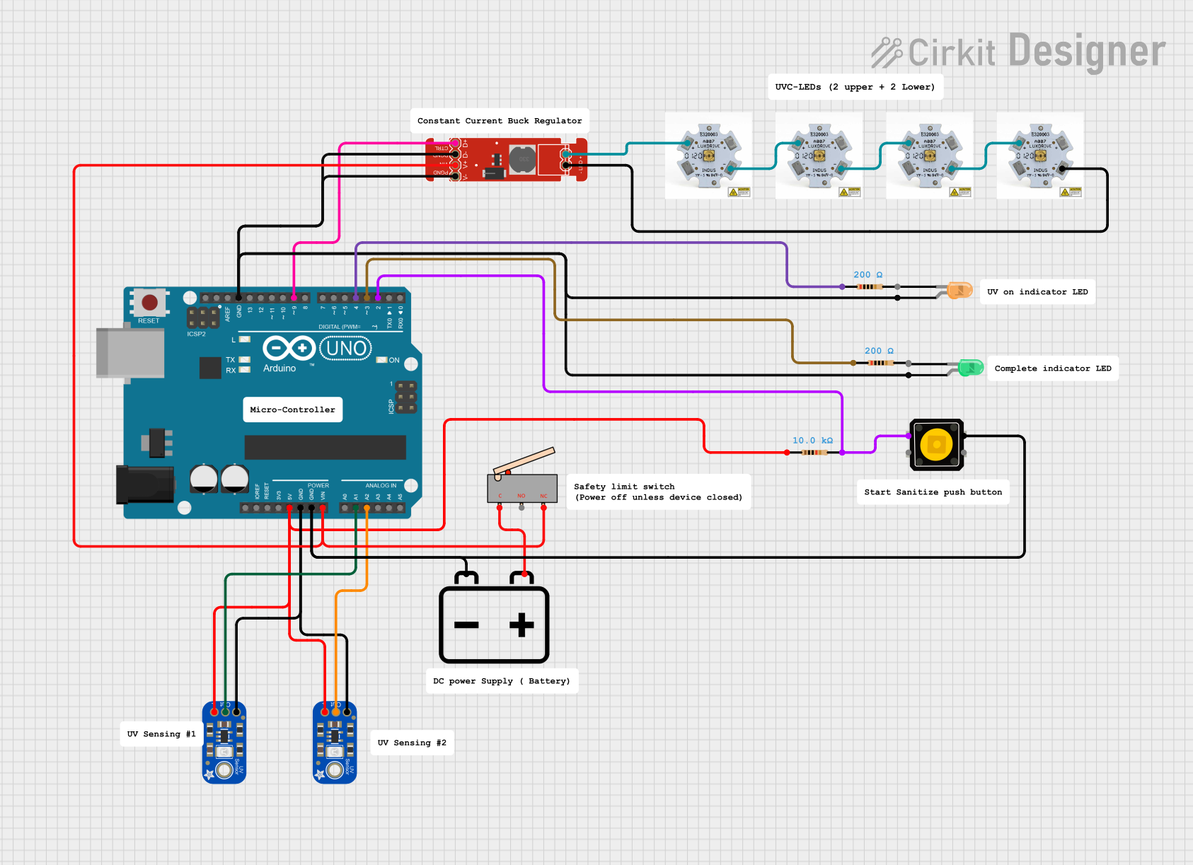
Example Circuit with Arduino UNO
The GOJJU 7017 UV LED can be controlled using an Arduino UNO. Below is an example circuit and code to blink the UV LED:
Circuit Diagram
- Connect the anode (+) of the UV LED to a 220Ω resistor.
- Connect the other end of the resistor to Arduino digital pin 9.
- Connect the cathode (-) of the UV LED to the Arduino GND pin.
Arduino Code
// UV LED Blink Example
// This code blinks the GOJJU 7017 UV LED connected to pin 9 of the Arduino UNO.

const int uvLedPin = 9; // Define the pin connected to the UV LED

void setup() {
  pinMode(uvLedPin, OUTPUT); // Set the UV LED pin as an output
}

void loop() {
  digitalWrite(uvLedPin, HIGH); // Turn the UV LED on
  delay(1000); // Wait for 1 second
  digitalWrite(uvLedPin, LOW); // Turn the UV LED off
  delay(1000); // Wait for 1 second
}
Important Considerations and Best Practices
- Eye Safety: UV light can be harmful to the eyes and skin. Always use appropriate protective gear when working with UV LEDs.
- Current Limiting: Always use a current-limiting resistor to prevent damage to the LED.
- Heat Dissipation: Prolonged use may generate heat. Use a heatsink or ensure proper ventilation to avoid overheating.
- Polarity Check: Connecting the LED with reversed polarity can damage the component.
Troubleshooting and FAQs
Common Issues and Solutions
LED Does Not Light Up:
- Cause: Incorrect polarity or insufficient voltage.
- Solution: Verify the anode and cathode connections. Ensure the power supply provides the required forward voltage.
LED Flickers or is Dim:
- Cause: Insufficient current or a loose connection.
- Solution: Check the resistor value and ensure all connections are secure.
LED Overheats:
- Cause: Excessive current or poor heat dissipation.
- Solution: Use a proper current-limiting resistor and ensure adequate cooling.
Arduino Code Does Not Work:
- Cause: Incorrect pin configuration or wiring.
- Solution: Double-check the circuit connections and ensure the correct pin is defined in the code.
FAQs
Q1: Can I power the UV LED directly from a 5V source?
A1: No, you must use a current-limiting resistor to prevent overcurrent damage.
Q2: What is the typical lifespan of the GOJJU 7017 UV LED?
A2: The typical lifespan is approximately 10,000 hours under recommended operating conditions.
Q3: Can I use the UV LED for water sterilization?
A3: While the GOJJU 7017 UV LED emits UV-A light, water sterilization typically requires UV-C light. This LED is not suitable for such applications.
Q4: How do I protect my eyes when working with UV LEDs?
A4: Always wear UV-blocking safety glasses and avoid direct exposure to the emitted light.
By following this documentation, you can safely and effectively use the GOJJU 7017 UV LED in your projects.