How to Use button 12x12: Examples, Pinouts, and Specs
Introduction
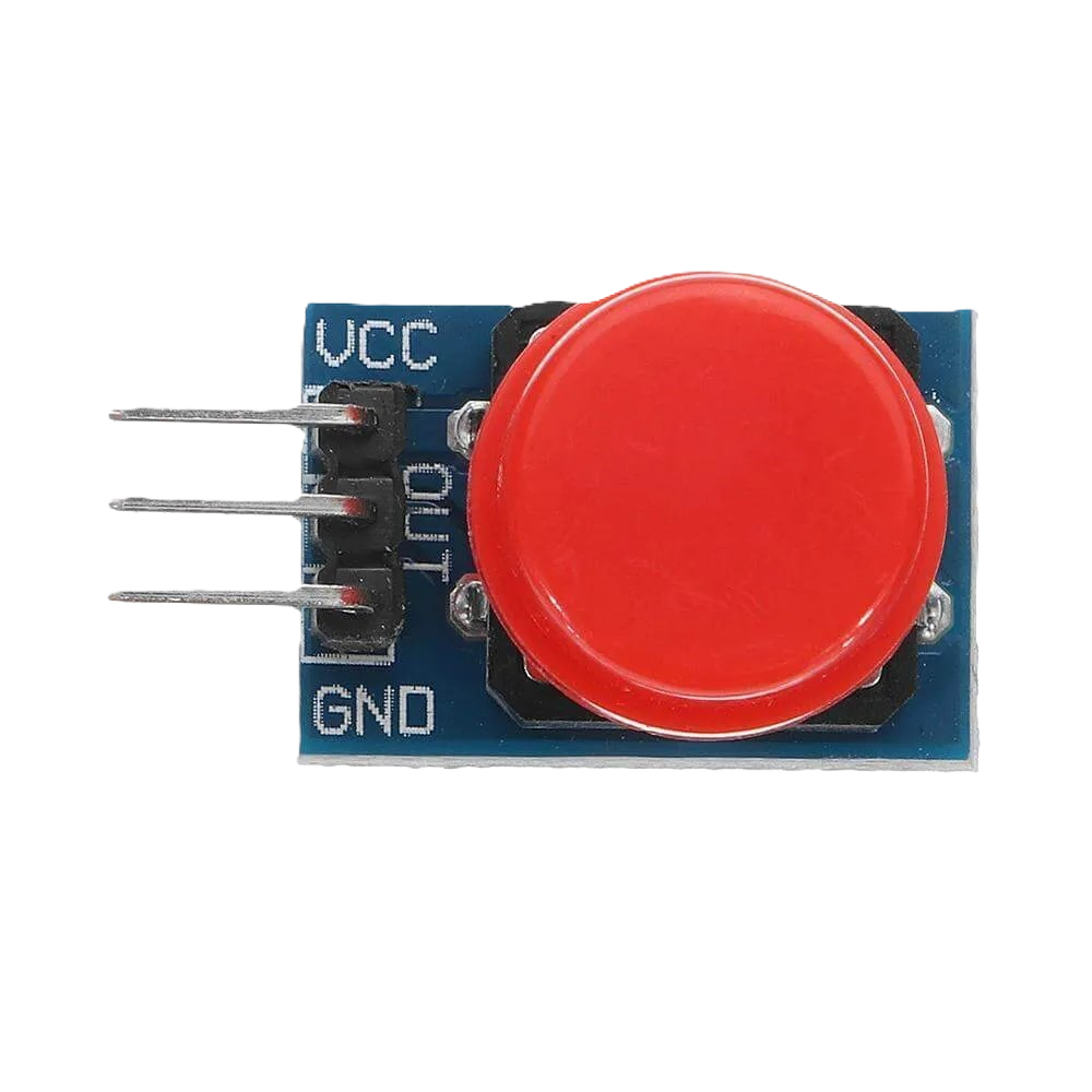
The Button 12x12 is a tactile push-button switch with a 12mm x 12mm footprint. It is widely used in electronic devices for user input, such as triggering actions, navigating menus, or resetting systems. This compact and durable switch is designed for through-hole mounting and provides a reliable tactile response when pressed.
Explore Projects Built with button 12x12

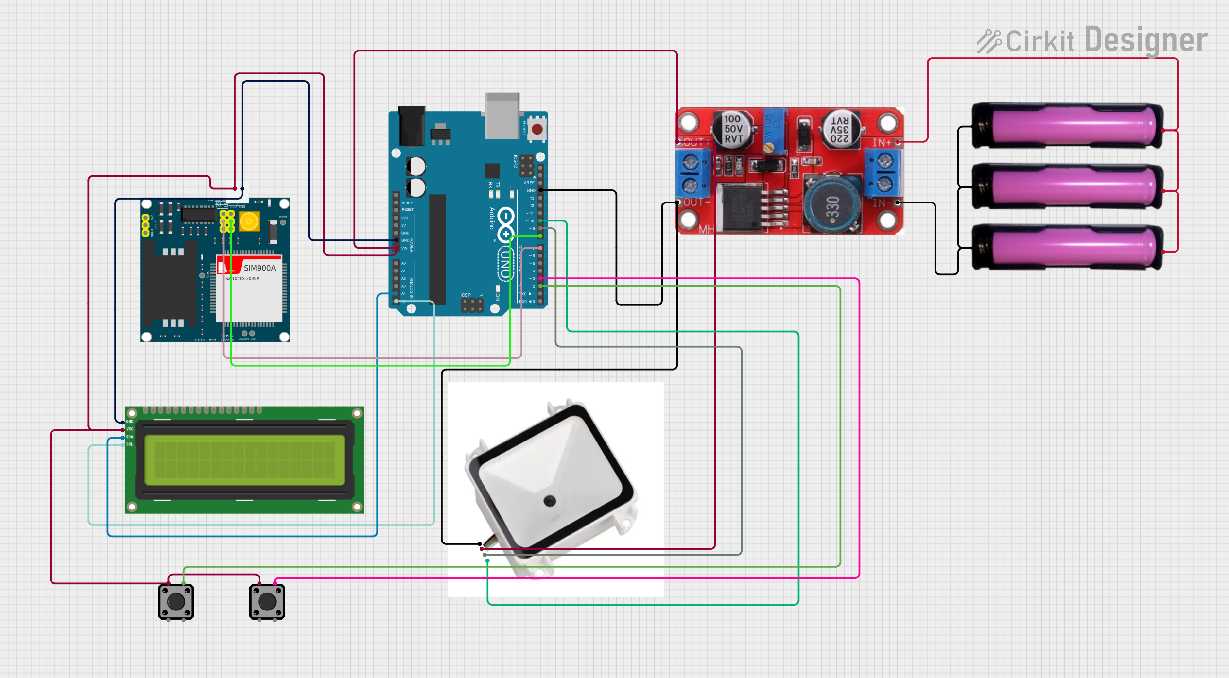

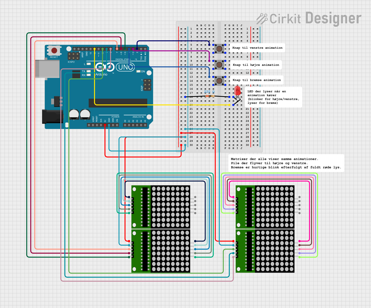
Explore Projects Built with button 12x12
Common Applications
- User input for microcontroller-based projects
- Reset or power buttons in electronic devices
- Menu navigation in embedded systems
- Prototyping and DIY electronics projects
Technical Specifications
The Button 12x12 is a simple yet versatile component. Below are its key technical details:
| Parameter | Value |
|---|---|
| Dimensions | 12mm x 12mm |
| Actuation Force | ~160-260 gf |
| Operating Voltage | 12V DC (maximum) |
| Operating Current | 50mA (maximum) |
| Contact Resistance | ≤ 100 mΩ |
| Insulation Resistance | ≥ 100 MΩ at 100V DC |
| Operating Temperature | -25°C to +70°C |
| Lifespan | ~100,000 cycles |
Pin Configuration
The Button 12x12 has four pins, arranged in a square configuration. The pins are internally connected in pairs, as shown below:
| Pin Number | Description |
|---|---|
| Pin 1 & Pin 2 | Connected internally (switch side 1) |
| Pin 3 & Pin 4 | Connected internally (switch side 2) |
Note: When the button is not pressed, the two sides are electrically isolated. Pressing the button creates a connection between the two sides.
Usage Instructions
How to Use the Button 12x12 in a Circuit
- Identify the Pins: Use a multimeter to confirm the internal connections between the pins. Pins 1 and 2 are connected, and Pins 3 and 4 are connected.
- Connect to Circuit:
- Connect one side of the button (e.g., Pins 1 and 2) to the input signal or microcontroller pin.
- Connect the other side (e.g., Pins 3 and 4) to ground or the desired circuit path.
- Debounce the Button: Mechanical switches like the Button 12x12 can produce noise or "bouncing" when pressed. Use a capacitor (e.g., 0.1µF) or software debounce techniques to ensure stable operation.
Example: Connecting to an Arduino UNO
Below is an example of how to use the Button 12x12 with an Arduino UNO to toggle an LED:
Circuit Connections
- Connect one side of the button (Pins 1 and 2) to digital pin 2 on the Arduino.
- Connect the other side (Pins 3 and 4) to ground.
- Add a pull-up resistor (10kΩ) between digital pin 2 and 5V to ensure a stable HIGH signal when the button is not pressed.
- Connect an LED to digital pin 13 with a 220Ω resistor in series.
Arduino Code
// Define pin numbers
const int buttonPin = 2;  // Button connected to digital pin 2
const int ledPin = 13;    // LED connected to digital pin 13

// Variable to store button state
int buttonState = 0;

void setup() {
  pinMode(buttonPin, INPUT_PULLUP); // Set button pin as input with internal pull-up
  pinMode(ledPin, OUTPUT);         // Set LED pin as output
}

void loop() {
  // Read the button state
  buttonState = digitalRead(buttonPin);

  // Check if the button is pressed (LOW due to pull-up resistor)
  if (buttonState == LOW) {
    digitalWrite(ledPin, HIGH); // Turn on the LED
  } else {
    digitalWrite(ledPin, LOW);  // Turn off the LED
  }
}
Best Practices
- Always use a pull-up or pull-down resistor to avoid floating input signals.
- For long-term reliability, avoid exceeding the maximum voltage and current ratings.
- Use a debounce circuit or software to handle switch bouncing.
Troubleshooting and FAQs
Common Issues
Button Not Responding
- Cause: Incorrect wiring or loose connections.
- Solution: Double-check the pin connections and ensure the button is properly soldered or inserted into the breadboard.
Button Bouncing
- Cause: Mechanical noise when the button is pressed or released.
- Solution: Add a debounce circuit (e.g., capacitor) or implement software debounce in your code.
LED Stays ON/OFF
- Cause: Missing pull-up or pull-down resistor.
- Solution: Add a 10kΩ pull-up resistor between the input pin and 5V (or a pull-down resistor to ground, depending on your circuit).
FAQs
Q: Can I use the Button 12x12 with a 3.3V system?
A: Yes, the Button 12x12 is compatible with 3.3V systems as long as the current does not exceed 50mA.
Q: How do I test if the button is working?
A: Use a multimeter in continuity mode. Press the button and check if the two sides of the switch are connected.
Q: Can I use the Button 12x12 for high-power applications?
A: No, the Button 12x12 is designed for low-power applications. For high-power circuits, use a relay or a more robust switch.
Q: How do I mount the Button 12x12 on a PCB?
A: The Button 12x12 is designed for through-hole mounting. Insert the pins into the PCB holes and solder them securely.
By following this documentation, you can effectively integrate the Button 12x12 into your electronic projects!