How to Use 16-bit DAC: Examples, Pinouts, and Specs
Introduction
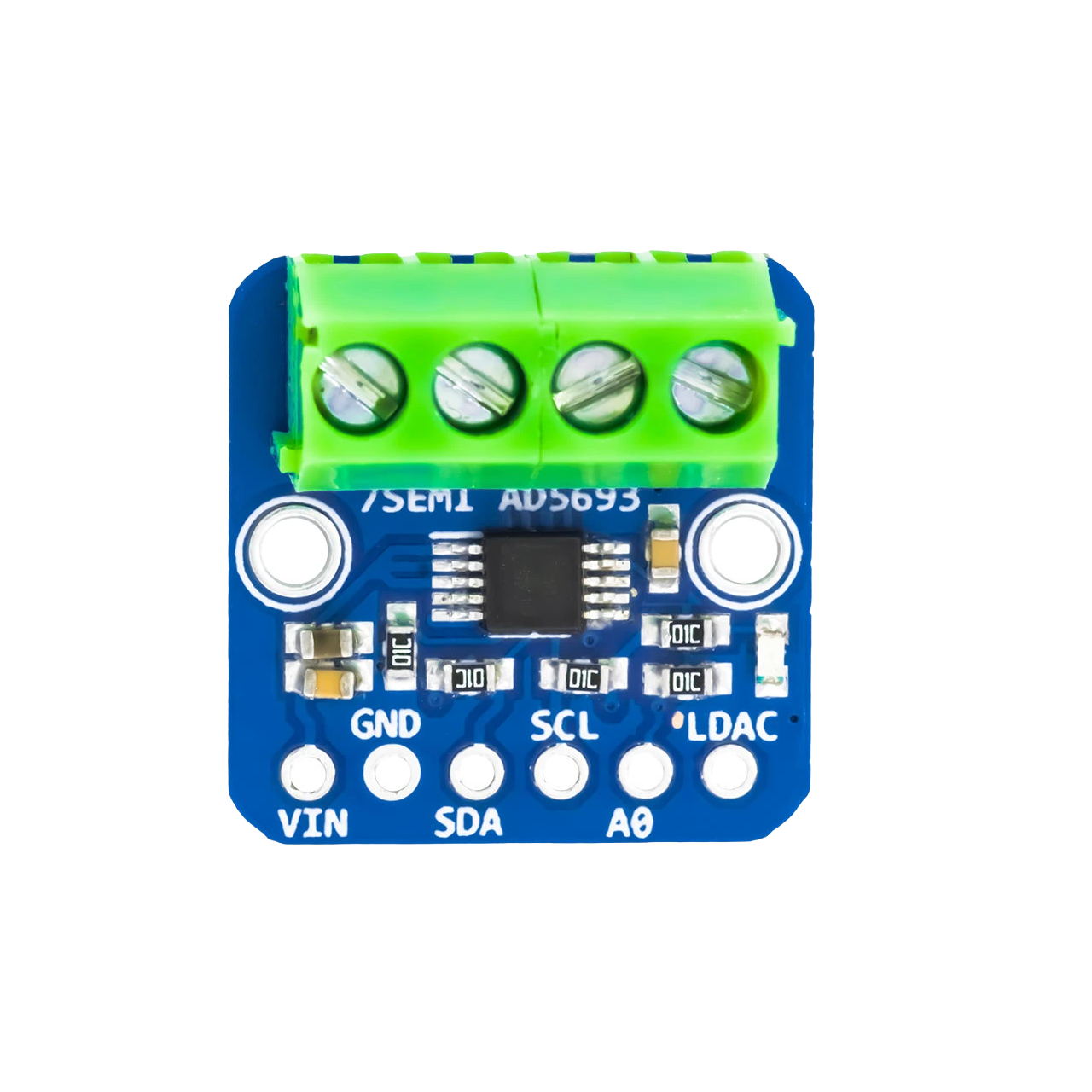
The AD5693, manufactured by 7SEMI, is a high-performance 16-bit Digital-to-Analog Converter (DAC) designed to convert digital signals into precise analog voltages. With its 16-bit resolution, the AD5693 ensures smooth signal transitions and fine control over output levels, making it ideal for applications requiring high accuracy and stability.
Explore Projects Built with 16-bit DAC

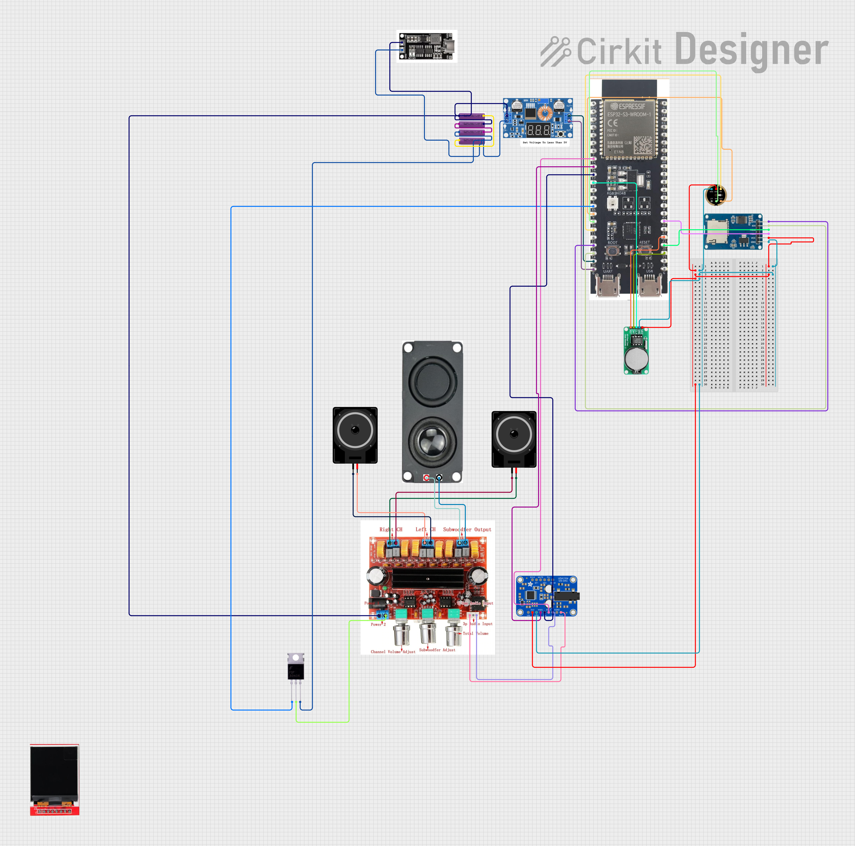
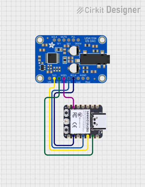
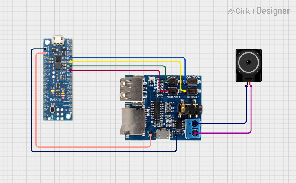
Explore Projects Built with 16-bit DAC
Common Applications and Use Cases
- Industrial process control
- Precision instrumentation
- Signal generation
- Data acquisition systems
- Audio signal processing
- Voltage reference generation
Technical Specifications
The AD5693 is a single-channel DAC with an I²C-compatible interface, offering excellent performance in a compact package.
Key Technical Details
| Parameter | Value |
|---|---|
| Resolution | 16 bits |
| Output Voltage Range | 0 V to VREF |
| Reference Voltage (VREF) | 2.5 V (typical) or external |
| Supply Voltage (VDD) | 2.7 V to 5.5 V |
| Power Consumption | 0.7 mW (typical at 3.3 V) |
| Interface | I²C (up to 400 kHz) |
| Output Type | Voltage output |
| Operating Temperature | -40°C to +125°C |
| Package | 8-lead MSOP or 8-lead LFCSP |
Pin Configuration and Descriptions
The AD5693 is available in an 8-pin package. Below is the pinout and description:
| Pin No. | Name | Description |
|---|---|---|
| 1 | VDD | Positive power supply (2.7 V to 5.5 V) |
| 2 | GND | Ground |
| 3 | SDA | I²C data line |
| 4 | SCL | I²C clock line |
| 5 | VOUT | Analog output voltage |
| 6 | VREF | Reference voltage input (internal or external) |
| 7 | A0 | I²C address selection pin |
| 8 | NC | No connection |
Usage Instructions
The AD5693 is straightforward to use in a circuit, thanks to its I²C interface and flexible voltage reference options. Below are the steps and considerations for integrating the DAC into your design.
Connecting the AD5693
- Power Supply: Connect the VDD pin to a stable power source (2.7 V to 5.5 V) and the GND pin to ground.
- I²C Interface: Connect the SDA and SCL pins to the corresponding I²C lines of your microcontroller. Use pull-up resistors (typically 4.7 kΩ) on both lines.
- Reference Voltage: Provide a reference voltage to the VREF pin. You can use the internal 2.5 V reference or an external reference for higher precision.
- Output: Connect the VOUT pin to the desired load or circuit.
Important Considerations
- Ensure the I²C address is correctly set using the A0 pin. The default address is
0x0C, but it can be modified by connecting A0 to VDD or GND. - Use decoupling capacitors (e.g., 0.1 µF and 10 µF) close to the VDD pin to minimize noise.
- Avoid exceeding the maximum voltage ratings to prevent damage to the device.
Example: Using AD5693 with Arduino UNO
Below is an example of how to interface the AD5693 with an Arduino UNO to output a specific voltage.
#include <Wire.h> // Include the Wire library for I²C communication

#define DAC_ADDRESS 0x0C // Default I²C address of the AD5693

void setup() {
  Wire.begin(); // Initialize I²C communication
  Serial.begin(9600); // Initialize serial communication for debugging
}

void loop() {
  uint16_t dacValue = 32768; // 16-bit value (e.g., mid-scale for 2.5V reference)
  writeDAC(dacValue); // Write the value to the DAC
  delay(1000); // Wait for 1 second
}

// Function to write a 16-bit value to the AD5693
void writeDAC(uint16_t value) {
  Wire.beginTransmission(DAC_ADDRESS); // Start communication with the DAC
  Wire.write(0x30); // Command to write to the DAC register
  Wire.write(value >> 8); // Send the upper 8 bits of the value
  Wire.write(value & 0xFF); // Send the lower 8 bits of the value
  Wire.endTransmission(); // End communication

  Serial.print("DAC Value Written: ");
  Serial.println(value); // Print the written value for debugging
}
Notes:
- The
dacValuevariable determines the output voltage. For example, with a 2.5 V reference, a value of32768corresponds to 1.25 V (mid-scale). - Adjust the I²C address (
DAC_ADDRESS) if the A0 pin configuration changes.
Troubleshooting and FAQs
Common Issues
No Output Voltage:
- Verify the power supply and ground connections.
- Check the I²C connections and ensure pull-up resistors are present.
- Confirm the reference voltage is applied correctly.
Incorrect Output Voltage:
- Ensure the correct 16-bit value is being sent to the DAC.
- Verify the reference voltage matches the expected value.
I²C Communication Failure:
- Check the I²C address and ensure it matches the configuration of the A0 pin.
- Confirm the SDA and SCL lines are not shorted or disconnected.
FAQs
Q: Can I use an external reference voltage?
A: Yes, the AD5693 supports external reference voltages for improved accuracy. Ensure the voltage does not exceed the supply voltage.
Q: What is the maximum output current of the DAC?
A: The AD5693 can source or sink up to 10 mA. For higher loads, use a buffer amplifier.
Q: How do I calculate the output voltage?
A: The output voltage is calculated as:
[
V_{OUT} = \left(\frac{\text{DAC Value}}{2^{16}}\right) \times V_{REF}
]
For example, with a DAC value of 32768 and a reference voltage of 2.5 V, the output voltage is 1.25 V.
Q: Can I use the AD5693 with a 5 V microcontroller?
A: Yes, the AD5693 supports supply voltages up to 5.5 V, making it compatible with 5 V systems. Ensure the I²C lines are properly level-shifted if needed.
By following this documentation, you can effectively integrate the AD5693 into your projects for precise digital-to-analog conversion.