How to Use TM1637: Examples, Pinouts, and Specs
Introduction
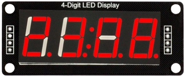
The TM1637 is a versatile 7-segment display driver designed to control up to 6 digits. Manufactured by Arduino, this component simplifies the process of driving numeric displays by using a two-wire interface (CLK and DIO). It is widely used in applications such as digital clocks, counters, temperature displays, and other projects requiring numeric or alphanumeric output.
The TM1637 is particularly popular in hobbyist and educational projects due to its ease of use, low power consumption, and compatibility with microcontrollers like the Arduino UNO.
Explore Projects Built with TM1637

Explore Projects Built with TM1637
Technical Specifications
The TM1637 has the following key technical specifications:
| Parameter | Value |
|---|---|
| Operating Voltage | 3.3V to 5.5V |
| Operating Current | < 1.5mA (typical) |
| Interface Type | Two-wire (CLK and DIO) |
| Maximum Digits | 6 |
| Display Type | Common cathode 7-segment displays |
| Brightness Levels | 8 adjustable levels |
| Operating Temperature | -40°C to +85°C |
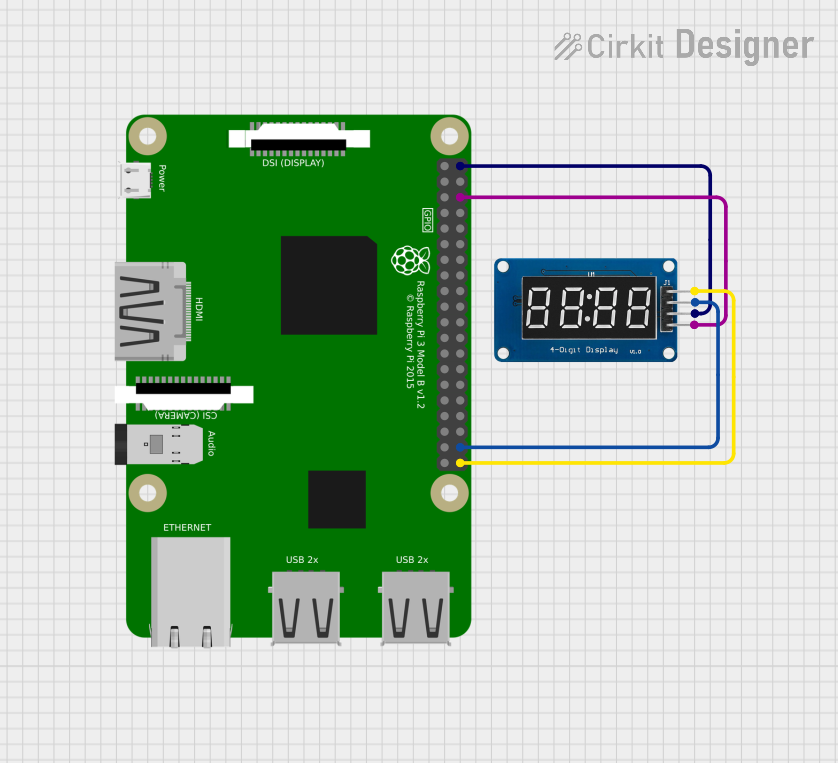
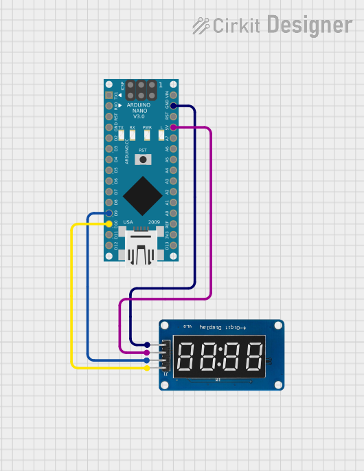
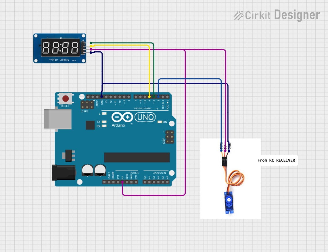
Pin Configuration
The TM1637 module typically has 4 pins, which are described in the table below:
| Pin | Name | Description |
|---|---|---|
| 1 | VCC | Power supply pin. Connect to 3.3V or 5V. |
| 2 | GND | Ground pin. Connect to the ground of the circuit. |
| 3 | DIO | Data I/O pin. Used for communication with the microcontroller. |
| 4 | CLK | Clock pin. Used for synchronizing data transfer between the module and the MCU. |
Usage Instructions
Connecting the TM1637 to an Arduino UNO
To use the TM1637 with an Arduino UNO, follow these steps:
- Connect the
VCCpin of the TM1637 to the 5V pin on the Arduino. - Connect the
GNDpin of the TM1637 to the GND pin on the Arduino. - Connect the
DIOpin of the TM1637 to a digital pin on the Arduino (e.g., D2). - Connect the
CLKpin of the TM1637 to another digital pin on the Arduino (e.g., D3).
Example Code
Below is an example Arduino sketch to display numbers on a 4-digit TM1637 module. This code uses the TM1637Display library, which simplifies communication with the module.
#include <TM1637Display.h>

// Define the CLK and DIO pins connected to the TM1637
#define CLK 3  // Clock pin
#define DIO 2  // Data I/O pin

// Initialize the TM1637 display object
TM1637Display display(CLK, DIO);

void setup() {
  // Set the brightness of the display (0 to 7)
  display.setBrightness(5);

  // Display a test pattern (e.g., "1234")
  display.showNumberDec(1234);
}

void loop() {
  // Example: Display a counter that increments every second
  for (int i = 0; i <= 9999; i++) {
    display.showNumberDec(i);  // Display the number
    delay(1000);               // Wait for 1 second
  }
}
Important Considerations
- Ensure the TM1637 module is powered within its operating voltage range (3.3V to 5.5V).
- Use pull-up resistors on the
DIOandCLKlines if communication issues occur. - Avoid driving the display at maximum brightness for extended periods to prevent overheating.
Troubleshooting and FAQs
Common Issues
The display does not light up.
- Verify that the
VCCandGNDpins are correctly connected to the power supply. - Check the voltage level to ensure it is within the operating range (3.3V to 5.5V).
- Verify that the
The display shows incorrect or garbled numbers.
- Ensure the
DIOandCLKpins are correctly connected to the Arduino. - Verify that the correct pins are defined in the code (
#define CLKand#define DIO).
- Ensure the
The display is too dim or too bright.
- Adjust the brightness level in the code using
display.setBrightness().
- Adjust the brightness level in the code using
The display does not update.
- Check the connections for loose wires or poor soldering.
- Ensure the Arduino sketch is correctly uploaded and running.
Tips for Troubleshooting
- Use a multimeter to check the voltage at the
VCCandGNDpins. - Test the module with a simple sketch to isolate hardware issues.
- If using a long cable for
DIOandCLK, consider adding pull-up resistors (10kΩ) to improve signal integrity.
By following this documentation, you can effectively integrate the TM1637 into your projects and troubleshoot common issues with ease.