How to Use DC to AC: Examples, Pinouts, and Specs
Introduction
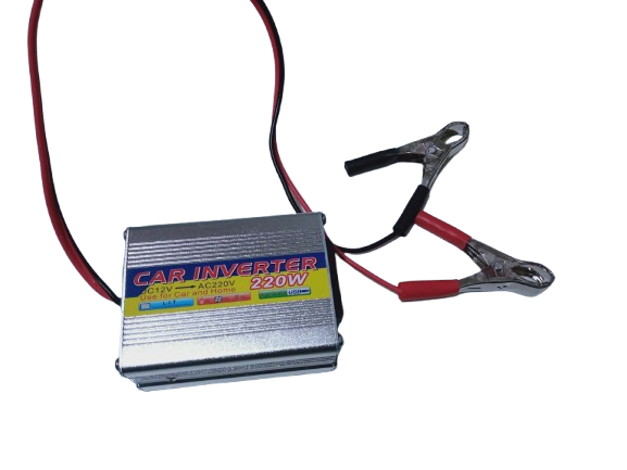
A DC to AC converter, commonly referred to as an inverter, is an electronic device that transforms direct current (DC) from sources such as batteries or solar panels into alternating current (AC). This conversion enables the use of DC power sources to operate AC appliances, tools, and other devices that require AC power.
Explore Projects Built with DC to AC


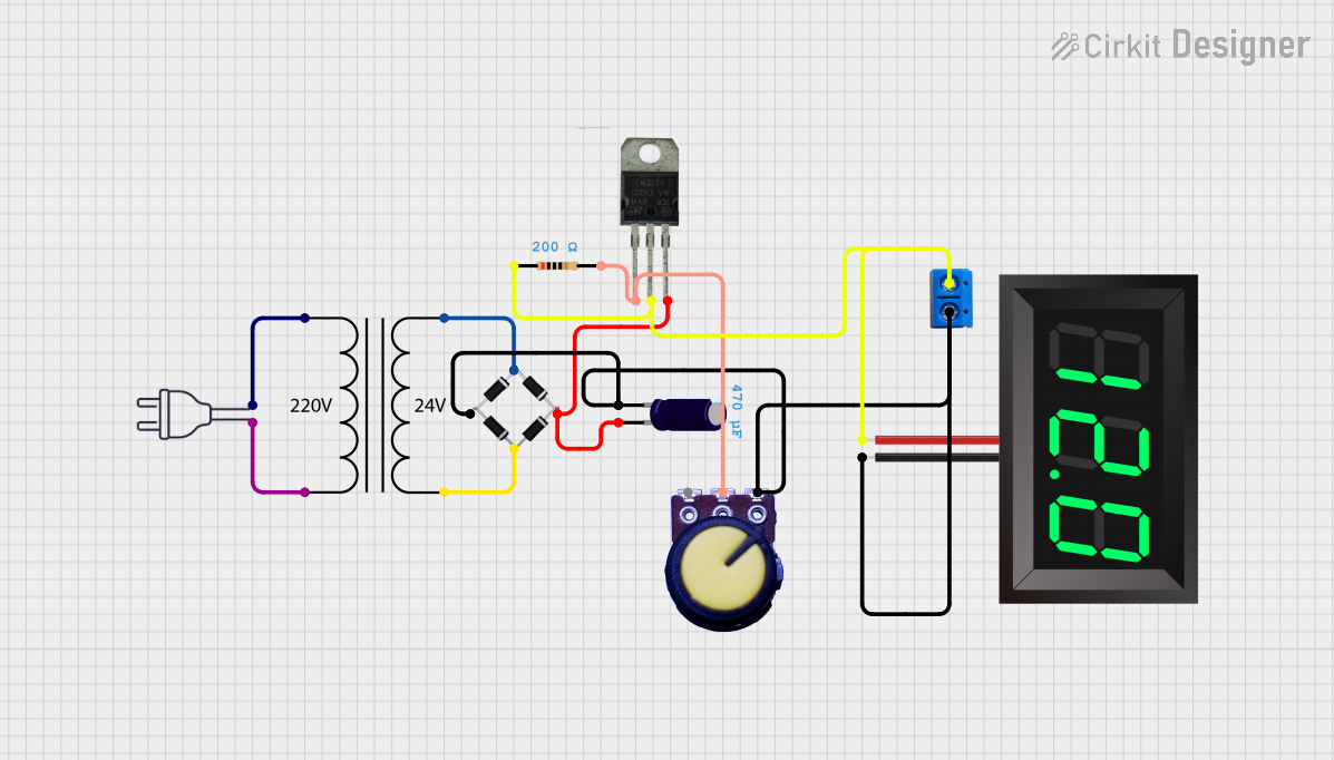
Explore Projects Built with DC to AC
Common Applications and Use Cases
- Powering household appliances using solar energy systems
- Running AC devices in vehicles or off-grid locations
- Emergency backup power systems
- Industrial and commercial applications requiring AC power from DC sources
Technical Specifications
Below are the general technical specifications for a typical DC to AC converter. Note that actual values may vary depending on the specific model or manufacturer.
| Parameter | Specification |
|---|---|
| Input Voltage Range | 12V DC, 24V DC, or 48V DC (varies by model) |
| Output Voltage | 110V AC or 220V AC (depending on region) |
| Output Frequency | 50Hz or 60Hz |
| Output Waveform | Pure Sine Wave, Modified Sine Wave, or Square Wave |
| Efficiency | 85% to 95% |
| Power Rating | 100W to 5000W (or higher for industrial models) |
| Protection Features | Overload, short circuit, over-temperature, low voltage, and overvoltage protection |
Pin Configuration and Descriptions
The DC to AC converter typically has the following input and output connections:
| Pin/Terminal | Description |
|---|---|
| DC Input (+) | Positive terminal for DC input voltage |
| DC Input (-) | Negative terminal for DC input voltage |
| AC Output (L) | Live (hot) terminal for AC output |
| AC Output (N) | Neutral terminal for AC output |
| Ground (GND) | Ground connection for safety |
Usage Instructions
How to Use the Component in a Circuit
Connect the DC Input:
- Ensure the DC power source (e.g., battery or solar panel) matches the input voltage range of the converter.
- Connect the positive terminal of the DC source to the DC Input (+) pin and the negative terminal to the DC Input (-) pin.
Connect the AC Output:
- Connect the AC Output (L) and (N) terminals to the AC appliance or load.
- If required, connect the Ground (GND) terminal to the earth ground for safety.
Power On:
- Turn on the DC power source and then switch on the inverter (if it has a power switch).
- Verify that the AC output voltage and frequency match the requirements of the connected appliance.
Important Considerations and Best Practices
- Input Voltage: Always ensure the DC input voltage is within the specified range to avoid damage to the converter.
- Load Capacity: Do not exceed the power rating of the converter. Overloading can cause overheating or failure.
- Waveform Type: Use a pure sine wave inverter for sensitive electronics, as modified or square wave inverters may cause interference or damage.
- Ventilation: Place the converter in a well-ventilated area to prevent overheating.
- Safety: Use proper fuses or circuit breakers on the DC input side to protect against short circuits.
Example: Using a DC to AC Converter with an Arduino UNO
While DC to AC converters are not directly controlled by an Arduino, you can use an Arduino to monitor or control the DC input or AC output. Below is an example of using an Arduino to monitor the DC input voltage of the converter.
// Example: Monitoring DC Input Voltage of a DC to AC Converter
// This code reads the DC input voltage using an analog pin and displays it on the Serial Monitor.

const int voltagePin = A0; // Analog pin connected to the DC input voltage divider
const float voltageDividerRatio = 11.0; // Ratio of the voltage divider (e.g., 10k:1k)

void setup() {
  Serial.begin(9600); // Initialize serial communication at 9600 baud
  pinMode(voltagePin, INPUT); // Set the voltage pin as input
}

void loop() {
  int sensorValue = analogRead(voltagePin); // Read the analog value
  float voltage = (sensorValue * 5.0 / 1023.0) * voltageDividerRatio;
  // Convert the analog value to voltage using the divider ratio

  Serial.print("DC Input Voltage: ");
  Serial.print(voltage);
  Serial.println(" V");

  delay(1000); // Wait for 1 second before the next reading
}
Note: Use a voltage divider circuit to step down the DC input voltage to a safe level (0-5V) for the Arduino's analog input pin.
Troubleshooting and FAQs
Common Issues and Solutions
No Output Voltage:
- Cause: Incorrect DC input connection or insufficient input voltage.
- Solution: Verify the DC input polarity and ensure the input voltage is within the specified range.
Overheating:
- Cause: Overloading or poor ventilation.
- Solution: Reduce the load or move the converter to a well-ventilated area.
Appliance Not Working Properly:
- Cause: Incompatible output waveform (e.g., modified sine wave).
- Solution: Use a pure sine wave inverter for sensitive devices.
Frequent Shutdowns:
- Cause: Low input voltage or over-temperature protection.
- Solution: Check the DC power source and ensure proper cooling.
FAQs
Q: Can I use a DC to AC converter with a car battery?
A: Yes, as long as the converter's input voltage matches the car battery's voltage (typically 12V) and the load does not exceed the converter's power rating.
Q: What is the difference between pure sine wave and modified sine wave inverters?
A: Pure sine wave inverters produce a smooth, sinusoidal AC output, suitable for all devices. Modified sine wave inverters produce a stepped waveform, which may not be compatible with sensitive electronics.
Q: How do I calculate the required power rating for my inverter?
A: Add up the power ratings (in watts) of all devices you plan to connect and choose an inverter with a power rating at least 20-30% higher than the total load.
Q: Can I connect solar panels directly to a DC to AC converter?
A: No, you need a solar charge controller and a battery to regulate the voltage and provide a stable DC input to the converter.