
How to Use PC-817: Examples, Pinouts, and Specs
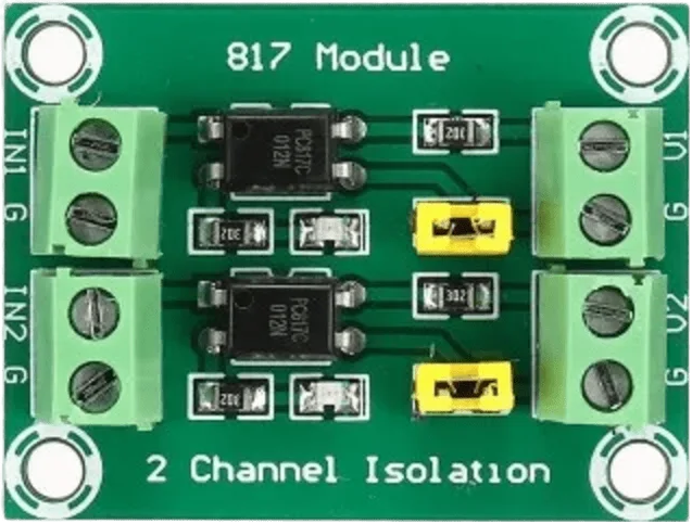
 Design with PC-817 in Cirkit Designer
Introduction
The PC-817 is an optoisolator (or optocoupler) that combines a light-emitting diode (LED) and a phototransistor in a single compact package. It is designed to transfer electrical signals between two isolated circuits while providing electrical isolation. This isolation protects sensitive components from high voltages, electrical noise, and ground loops, making the PC-817 an essential component in many electronic designs.
Explore Projects Built with PC-817
 Open Project in Cirkit Designer
 Open Project in Cirkit Designer
 Open Project in Cirkit Designer
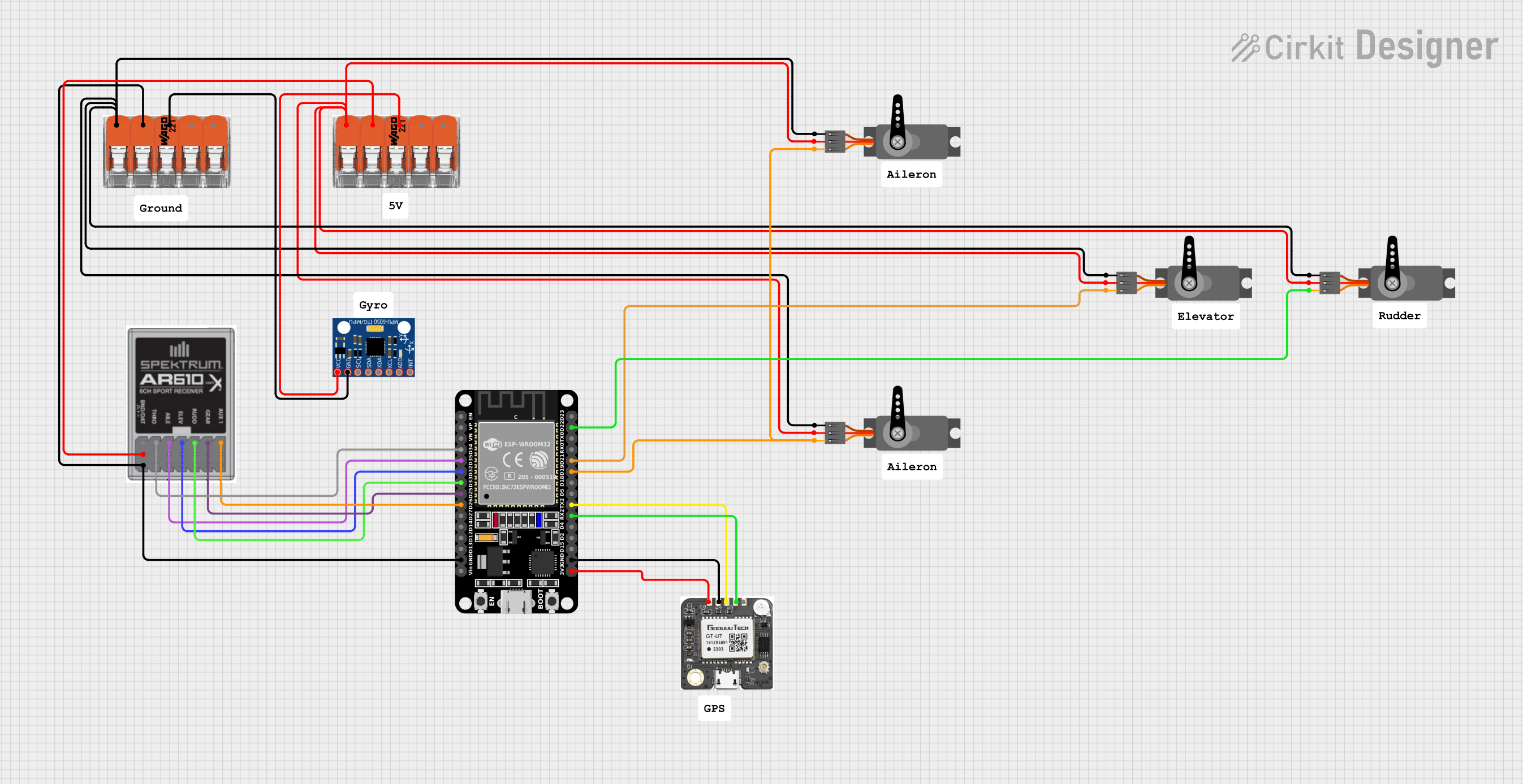 Open Project in Cirkit Designer
Explore Projects Built with PC-817
Open Project in Cirkit DesignerOpen Project in Cirkit DesignerOpen Project in Cirkit DesignerOpen Project in Cirkit DesignerCommon Applications and Use Cases
- Microcontroller interfacing with high-voltage circuits
- Signal isolation in industrial control systems
- Switching power supplies
- Motor control circuits
- Noise suppression in communication systems
Technical Specifications
Below are the key technical details of the PC-817:
| Parameter | Value |
|---|---|
| Input Forward Voltage (VF) | 1.2V (typical), 1.4V (maximum) |
| Input Forward Current (IF) | 20mA (typical), 50mA (maximum) |
| Output Collector-Emitter Voltage (VCEO) | 35V (maximum) |
| Output Collector Current (IC) | 50mA (maximum) |
| Isolation Voltage | 5000Vrms (minimum) |
| Current Transfer Ratio (CTR) | 50% to 600% (depending on model) |
| Operating Temperature Range | -30°C to +100°C |
| Package Type | 4-pin DIP |
Pin Configuration and Descriptions
The PC-817 has a 4-pin configuration, as shown below:
| Pin Number | Name | Description |
|---|---|---|
| 1 | Anode (A) | Positive terminal of the internal LED |
| 2 | Cathode (K) | Negative terminal of the internal LED |
| 3 | Emitter (E) | Emitter of the phototransistor |
| 4 | Collector (C) | Collector of the phototransistor |
Usage Instructions
How to Use the PC-817 in a Circuit
Input Side (LED):
- Connect the anode (Pin 1) to the positive side of the input signal through a current-limiting resistor.
- Connect the cathode (Pin 2) to the ground of the input circuit.
- Choose the resistor value to limit the forward current (IF) to a safe level, typically 10-20mA.
Example resistor calculation: [ R = \frac{V_{in} - V_F}{I_F} ] Where:
- ( V_{in} ) is the input voltage
- ( V_F ) is the forward voltage of the LED (1.2V typical)
- ( I_F ) is the desired forward current (e.g., 10mA)
Output Side (Phototransistor):
- Connect the collector (Pin 4) to the positive voltage supply through a pull-up resistor.
- Connect the emitter (Pin 3) to the ground of the output circuit.
- The pull-up resistor value depends on the desired output current and voltage levels.
Circuit Example: Below is a basic circuit diagram for interfacing the PC-817 with a microcontroller:
Input Circuit:                     Output Circuit:
+5V ----[Resistor]----|> (LED)     +5V ----[Pull-up Resistor]----(Collector)
                             |                                    |
                            GND                                (Emitter)
Important Considerations and Best Practices
- Ensure the input current does not exceed the maximum forward current (50mA).
- Use a pull-up resistor on the output side to ensure proper signal levels.
- Avoid exceeding the maximum collector-emitter voltage (35V).
- For high-speed switching, consider the phototransistor's response time and adjust the circuit accordingly.
- Maintain proper isolation between the input and output circuits to prevent electrical interference.
Arduino UNO Example Code
The PC-817 can be easily interfaced with an Arduino UNO for signal isolation. Below is an example code to read the output of the PC-817:
// Define the input pin connected to the PC-817's output
const int optoInputPin = 2; // Digital pin 2

void setup() {
  pinMode(optoInputPin, INPUT); // Set the pin as input
  Serial.begin(9600); // Initialize serial communication
}

void loop() {
  int optoState = digitalRead(optoInputPin); // Read the optoisolator's state

  // Print the state to the Serial Monitor
  if (optoState == HIGH) {
    Serial.println("Signal HIGH: Optoisolator is ON");
  } else {
    Serial.println("Signal LOW: Optoisolator is OFF");
  }

  delay(500); // Delay for readability
}
Troubleshooting and FAQs
Common Issues and Solutions
No Output Signal:
- Cause: Insufficient input current to the LED.
- Solution: Check the input resistor value and ensure the forward current is within the recommended range (10-20mA).
Output Signal is Always HIGH or LOW:
- Cause: Incorrect pull-up resistor value or improper wiring.
- Solution: Verify the pull-up resistor value and ensure proper connections to the collector and emitter.
Signal Distortion or Noise:
- Cause: High-speed switching or electrical interference.
- Solution: Add a capacitor across the output to filter noise or use a shielded cable for connections.
Component Overheating:
- Cause: Excessive input current or output current.
- Solution: Ensure the input and output currents are within the specified limits.
FAQs
Q1: Can the PC-817 handle AC signals?
A1: Yes, the PC-817 can handle AC signals on the input side, but you must use a rectifier circuit to ensure proper operation.
Q2: What is the maximum isolation voltage of the PC-817?
A2: The PC-817 provides a minimum isolation voltage of 5000Vrms, making it suitable for high-voltage applications.
Q3: Can I use the PC-817 for high-speed switching?
A3: The PC-817 is suitable for moderate-speed applications. For high-speed switching, consider using optoisolators designed specifically for high-speed operation.
Q4: How do I calculate the pull-up resistor value?
A4: The pull-up resistor value depends on the desired output current and voltage. A typical value is 10kΩ for most applications.
By following this documentation, you can effectively use the PC-817 optoisolator in your electronic projects!