Cirkit Designer
Your all-in-one circuit design IDE
Home /
Component Documentation
How to Use AC-DC PSU board 220V-5V&12V: Examples, Pinouts, and Specs
Introduction
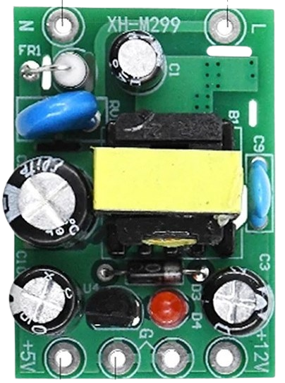
The AC-DC PSU (Power Supply Unit) board 220V-5V&12V is an electronic component designed to convert 220V AC power to two separate DC voltages: 5V and 12V. This board is commonly used in various electronic projects and applications where dual DC voltage levels are required, such as powering sensors, microcontrollers, and other electronic devices.
Explore Projects Built with AC-DC PSU board 220V-5V&12V
Wi-Fi Enabled AC Power Switch with RTL8720DN and 5V Relay
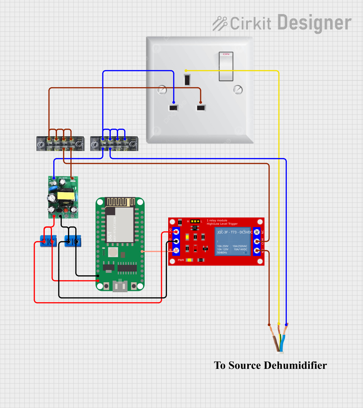
This circuit is designed to control an AC load using a 5V relay module, which is driven by a RTL8720DN microcontroller. The AC-DC PSU board converts 220V AC to 5V DC to power the microcontroller and the relay module. The microcontroller can switch the relay to turn the connected AC load on or off.
AC to DC Power Supply with 7-Segment Voltage Display

This circuit is a regulated power supply that converts 220V AC to a lower, stable DC voltage. It includes a step-down transformer, bridge rectifier, voltage regulator, and filtering capacitors. A 7-segment display indicates the output voltage, which can be adjusted using a potentiometer.
220V to 5V Power Supply with Transformer and Bridge Rectifier

This circuit converts 220V AC power to a 5V DC output. It uses a transformer to step down the voltage, a bridge rectifier to convert AC to DC, and a capacitor to smooth the output. The final 5V DC is available through a connector.
24V to 5V Power Supply Using 7805 and Bridge Rectifier
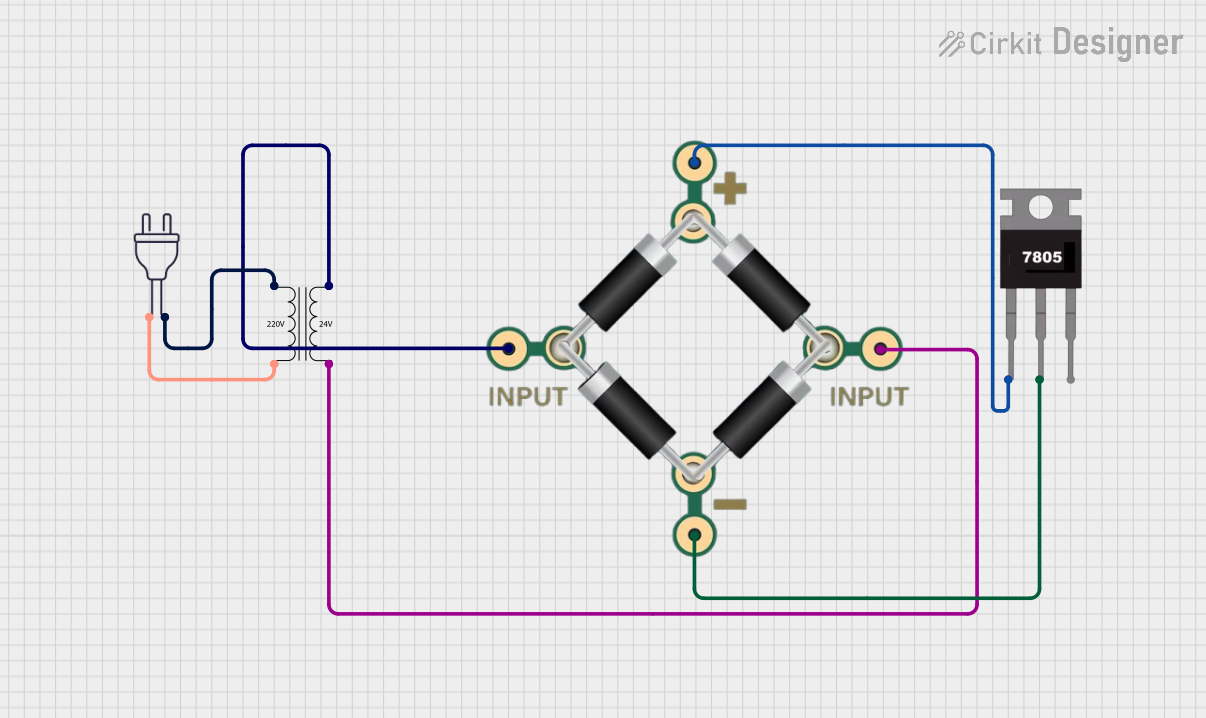
This circuit converts a 220V AC input to a regulated 5V DC output. It uses a power transformer to step down the voltage to 24V AC, which is then rectified by a bridge rectifier and regulated by a 7805 voltage regulator.
Explore Projects Built with AC-DC PSU board 220V-5V&12V
Wi-Fi Enabled AC Power Switch with RTL8720DN and 5V Relay
This circuit is designed to control an AC load using a 5V relay module, which is driven by a RTL8720DN microcontroller. The AC-DC PSU board converts 220V AC to 5V DC to power the microcontroller and the relay module. The microcontroller can switch the relay to turn the connected AC load on or off.
AC to DC Power Supply with 7-Segment Voltage Display
This circuit is a regulated power supply that converts 220V AC to a lower, stable DC voltage. It includes a step-down transformer, bridge rectifier, voltage regulator, and filtering capacitors. A 7-segment display indicates the output voltage, which can be adjusted using a potentiometer.
220V to 5V Power Supply with Transformer and Bridge Rectifier
This circuit converts 220V AC power to a 5V DC output. It uses a transformer to step down the voltage, a bridge rectifier to convert AC to DC, and a capacitor to smooth the output. The final 5V DC is available through a connector.
24V to 5V Power Supply Using 7805 and Bridge Rectifier
This circuit converts a 220V AC input to a regulated 5V DC output. It uses a power transformer to step down the voltage to 24V AC, which is then rectified by a bridge rectifier and regulated by a 7805 voltage regulator.
Common Applications and Use Cases
- DIY electronics projects
- Microcontroller-based systems (e.g., Arduino, Raspberry Pi)
- Robotics
- Home automation systems
- Industrial control systems
Technical Specifications
Key Technical Details
- Input Voltage: 220V AC
- Output Voltages: 5V DC and 12V DC
- Maximum Output Current: (specify for both 5V and 12V)
- Power Ratings: (specify for both 5V and 12V)
- Efficiency: (specify percentage)
- Isolation Voltage: (specify voltage)
- Operating Temperature Range: (specify range)
Pin Configuration and Descriptions
| Pin Number | Description | Voltage/Signal |
|---|---|---|
| 1 | AC Input (Live) | 220V AC |
| 2 | AC Input (Neutral) | 220V AC |
| 3 | Ground | - |
| 4 | 5V DC Output (+) | 5V DC |
| 5 | 5V DC Output (GND) | - |
| 6 | 12V DC Output (+) | 12V DC |
| 7 | 12V DC Output (GND) | - |
Usage Instructions
How to Use the Component in a Circuit
- Connect the AC input pins (1 and 2) to a 220V AC source. Ensure that the connection is secure and insulated to prevent electrical hazards.
- Connect the ground pin (3) to the earth ground of your system.
- Utilize the 5V DC and 12V DC outputs (pins 4, 5, 6, and 7) to power your electronic devices. Ensure that the current draw does not exceed the maximum output current specified for each voltage rail.
Important Considerations and Best Practices
- Always disconnect the power source before making any connections to the board.
- Verify the polarity of the DC outputs before connecting to your devices to prevent damage.
- Use appropriate fuses or circuit breakers to protect against overcurrent conditions.
- Ensure adequate ventilation around the board to prevent overheating.
- If integrating with a microcontroller like Arduino UNO, use a voltage level shifter if necessary to match the logic levels.
Troubleshooting and FAQs
Common Issues Users Might Face
- No Output Voltage: Check AC input connections and ensure the board is properly powered.
- Overheating: Ensure the current draw is within the specified limits and that there is adequate ventilation.
- Output Voltage Fluctuation: Verify that the AC source is stable and that there are no short circuits in the connected load.
Solutions and Tips for Troubleshooting
- If the output voltage is not stable, check for loose connections and consider adding a capacitor to smooth out the output.
- In case of no output, inspect the board for any visible damage or burnt components, which may indicate a short circuit or overload condition.
- Use a multimeter to measure the output voltages and ensure they are within the specified range.
FAQs
- Q: Can I use this board with a 110V AC source?
- A: No, this board is designed for 220V AC input only.
- Q: Is it safe to touch the board while it is powered?
- A: No, always ensure the power is off and the board is disconnected from the AC source before handling.
Example Code for Arduino UNO
// Example code to demonstrate how to use the 5V output from the PSU board to power an Arduino UNO

void setup() {
  // Initialize the digital pin as an output.
  pinMode(LED_BUILTIN, OUTPUT);
}

void loop() {
  // Turn the LED on (HIGH is the voltage level)
  digitalWrite(LED_BUILTIN, HIGH);
  // Wait for a second
  delay(1000);
  // Turn the LED off by making the voltage LOW
  digitalWrite(LED_BUILTIN, LOW);
  // Wait for a second
  delay(1000);
}
Note: This example assumes that the Arduino UNO is powered using the 5V output from the AC-DC PSU board. Always ensure that the voltage levels are compatible when connecting to any microcontroller.