Cirkit Designer Logo
Cirkit Designer
Your all-in-one circuit design IDE
Home / 
Component Documentation

How to Use 24v to 3.3v Octocoupler Moduler: Examples, Pinouts, and Specs

Image of 24v to 3.3v Octocoupler Moduler
Cirkit Designer LogoDesign with 24v to 3.3v Octocoupler Moduler in Cirkit Designer

Introduction

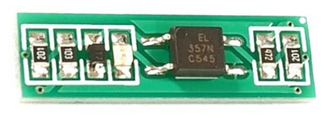
The 24V to 3.3V Optocoupler Module is a versatile electronic component designed to convert a 24V input signal to a 3.3V output signal. It achieves this while providing electrical isolation between the input and output, ensuring safe and reliable operation in circuits where different voltage levels need to interface. This module is commonly used in industrial automation, microcontroller interfacing, and signal level shifting applications.

Explore Projects Built with 24v to 3.3v Octocoupler Moduler

Use Cirkit Designer to design, explore, and prototype these projects online. Some projects support real-time simulation. Click "Open Project" to start designing instantly!
ESP32-Based Wi-Fi Controlled 24V Input/Output Interface Module
Image of ESP32 4 på rad: A project utilizing 24v to 3.3v Octocoupler Moduler in a practical application
This circuit uses an ESP32 microcontroller to interface with a 3.3V PNP to 24V NPN photoelectric isolation module, which in turn connects to a 40-pin connector for general-purpose input and output. The 24V power supply provides the necessary voltage for the isolation module and the 40-pin connector, enabling the ESP32 to control and monitor high-voltage signals safely.
Cirkit Designer LogoOpen Project in Cirkit Designer
Cellular-Connected ESP32-CAM with Real-Time Clock and Isolated Control
Image of LRCM PHASE 2 PRO: A project utilizing 24v to 3.3v Octocoupler Moduler in a practical application
This circuit integrates a LilyGo-SIM7000G module with an RTC DS3231 for timekeeping, interfaced via I2C (SCL and SDA lines). An 8-Channel OPTO-COUPLER is used to isolate and interface external signals with the LilyGo-SIM7000G's GPIOs. Power is managed by a Buck converter, which steps down voltage from a DC Power Source to supply the ESP32-CAM and LilyGo-SIM7000G modules, as well as the OPTO-COUPLER.
Cirkit Designer LogoOpen Project in Cirkit Designer
Cellular-Enabled IoT Device with Real-Time Clock and Power Management
Image of LRCM PHASE 2 BASIC: A project utilizing 24v to 3.3v Octocoupler Moduler in a practical application
This circuit features a LilyGo-SIM7000G module for cellular communication and GPS functionality, interfaced with an RTC DS3231 for real-time clock capabilities. It includes voltage sensing through two voltage sensor modules, and uses an 8-channel opto-coupler for isolating different parts of the circuit. Power management is handled by a buck converter connected to a DC power source and batteries, with a fuse for protection and a rocker switch for on/off control. Additionally, there's an LED for indication purposes.
Cirkit Designer LogoOpen Project in Cirkit Designer
Battery-Powered DC-DC Converter System for Multi-Voltage Power Distribution
Image of test 1 ih: A project utilizing 24v to 3.3v Octocoupler Moduler in a practical application
This circuit converts a 38.5V battery output to multiple lower voltage levels using a series of DC-DC converters and a power module. It includes an emergency stop switch for safety and distributes power to various components such as a relay module, USB ports, and a bus servo adaptor.
Cirkit Designer LogoOpen Project in Cirkit Designer

Explore Projects Built with 24v to 3.3v Octocoupler Moduler

Use Cirkit Designer to design, explore, and prototype these projects online. Some projects support real-time simulation. Click "Open Project" to start designing instantly!
Image of ESP32 4 på rad: A project utilizing 24v to 3.3v Octocoupler Moduler in a practical application
ESP32-Based Wi-Fi Controlled 24V Input/Output Interface Module
This circuit uses an ESP32 microcontroller to interface with a 3.3V PNP to 24V NPN photoelectric isolation module, which in turn connects to a 40-pin connector for general-purpose input and output. The 24V power supply provides the necessary voltage for the isolation module and the 40-pin connector, enabling the ESP32 to control and monitor high-voltage signals safely.
Cirkit Designer LogoOpen Project in Cirkit Designer
Image of LRCM PHASE 2 PRO: A project utilizing 24v to 3.3v Octocoupler Moduler in a practical application
Cellular-Connected ESP32-CAM with Real-Time Clock and Isolated Control
This circuit integrates a LilyGo-SIM7000G module with an RTC DS3231 for timekeeping, interfaced via I2C (SCL and SDA lines). An 8-Channel OPTO-COUPLER is used to isolate and interface external signals with the LilyGo-SIM7000G's GPIOs. Power is managed by a Buck converter, which steps down voltage from a DC Power Source to supply the ESP32-CAM and LilyGo-SIM7000G modules, as well as the OPTO-COUPLER.
Cirkit Designer LogoOpen Project in Cirkit Designer
Image of LRCM PHASE 2 BASIC: A project utilizing 24v to 3.3v Octocoupler Moduler in a practical application
Cellular-Enabled IoT Device with Real-Time Clock and Power Management
This circuit features a LilyGo-SIM7000G module for cellular communication and GPS functionality, interfaced with an RTC DS3231 for real-time clock capabilities. It includes voltage sensing through two voltage sensor modules, and uses an 8-channel opto-coupler for isolating different parts of the circuit. Power management is handled by a buck converter connected to a DC power source and batteries, with a fuse for protection and a rocker switch for on/off control. Additionally, there's an LED for indication purposes.
Cirkit Designer LogoOpen Project in Cirkit Designer
Image of test 1 ih: A project utilizing 24v to 3.3v Octocoupler Moduler in a practical application
Battery-Powered DC-DC Converter System for Multi-Voltage Power Distribution
This circuit converts a 38.5V battery output to multiple lower voltage levels using a series of DC-DC converters and a power module. It includes an emergency stop switch for safety and distributes power to various components such as a relay module, USB ports, and a bus servo adaptor.
Cirkit Designer LogoOpen Project in Cirkit Designer

Common Applications:

  • Interfacing industrial 24V control systems with 3.3V microcontrollers (e.g., Arduino, ESP32).
  • Signal isolation to protect sensitive components from high-voltage spikes.
  • Level shifting in mixed-voltage systems.
  • Noise suppression in communication lines.

Technical Specifications

Key Technical Details:

Parameter Value
Input Voltage Range 12V to 24V DC
Output Voltage 3.3V DC
Isolation Voltage Up to 2500V
Maximum Input Current 10mA
Output Current Capacity 10mA
Operating Temperature -40°C to 85°C
Dimensions Typically 25mm x 15mm x 10mm

Pin Configuration and Descriptions:

Pin Name Pin Type Description
VCC_IN Input Connect to the 24V DC input voltage.
GND_IN Input Ground connection for the input side.
VCC_OUT Output Provides the 3.3V output signal.
GND_OUT Output Ground connection for the output side.
SIGNAL_IN Input Input signal pin (24V logic level).
SIGNAL_OUT Output Output signal pin (3.3V logic level).

Usage Instructions

How to Use the Module in a Circuit:

  1. Power the Module:

    • Connect the VCC_IN pin to a 24V DC power source.
    • Connect the GND_IN pin to the ground of the 24V power source.
  2. Input Signal:

    • Feed the 24V logic signal to the SIGNAL_IN pin.
  3. Output Signal:

    • Connect the SIGNAL_OUT pin to the 3.3V logic input of your microcontroller or circuit.
    • Ensure the VCC_OUT and GND_OUT pins are connected to the 3.3V power rail and ground of the output circuit.
  4. Verify Connections:

    • Double-check all connections to ensure proper polarity and avoid damage.

Important Considerations:

  • Isolation: The module provides electrical isolation between the input and output. Ensure that the input and output grounds (GND_IN and GND_OUT) are not directly connected.
  • Input Voltage Range: Do not exceed the specified input voltage range (12V to 24V DC) to prevent damage to the module.
  • Output Current: The output current is limited to 10mA. Use an external transistor or driver circuit if higher current is required.

Example: Connecting to an Arduino UNO

Below is an example of how to connect the module to an Arduino UNO to read a 24V input signal.

Circuit Diagram:

  • VCC_IN → 24V DC power supply
  • GND_IN → Ground of the 24V power supply
  • SIGNAL_IN → 24V signal source
  • SIGNAL_OUT → Arduino digital input pin (e.g., D2)
  • VCC_OUT → Arduino 3.3V pin
  • GND_OUT → Arduino GND pin

Arduino Code Example:

// Define the input pin connected to the SIGNAL_OUT of the module
const int signalPin = 2;

void setup() {
  // Initialize the serial monitor for debugging
  Serial.begin(9600);

  // Set the signal pin as an input
  pinMode(signalPin, INPUT);
}

void loop() {
  // Read the state of the signal pin
  int signalState = digitalRead(signalPin);

  // Print the signal state to the serial monitor
  if (signalState == HIGH) {
    Serial.println("Signal HIGH (24V detected)");
  } else {
    Serial.println("Signal LOW (No 24V detected)");
  }

  // Add a small delay to avoid flooding the serial monitor
  delay(500);
}

Troubleshooting and FAQs

Common Issues and Solutions:

  1. No Output Signal:

    • Cause: Incorrect wiring or insufficient input voltage.
    • Solution: Verify that the VCC_IN pin is connected to a 24V DC source and that the SIGNAL_IN pin is receiving a valid 24V signal.
  2. Output Signal Not Detected by Microcontroller:

    • Cause: Incorrect connection to the microcontroller or incompatible logic levels.
    • Solution: Ensure the SIGNAL_OUT pin is connected to a 3.3V-compatible input pin on the microcontroller.
  3. Module Overheating:

    • Cause: Input voltage exceeds the specified range.
    • Solution: Check the input voltage and ensure it is within the 12V to 24V range.
  4. Ground Loops:

    • Cause: Input and output grounds are connected.
    • Solution: Ensure that GND_IN and GND_OUT are electrically isolated.

FAQs:

Q: Can this module be used with a 5V microcontroller?
A: No, this module is specifically designed for 3.3V logic levels. For 5V systems, use a level shifter or a different optocoupler module.

Q: Is the module bidirectional?
A: No, the module is unidirectional. It converts signals from 24V to 3.3V only.

Q: Can I use this module for AC signals?
A: No, this module is designed for DC signals only. Using it with AC signals may damage the module.

Q: What is the maximum switching frequency?
A: The module typically supports switching frequencies up to 10kHz, depending on the optocoupler used.

By following this documentation, you can effectively integrate the 24V to 3.3V Optocoupler Module into your projects for safe and reliable signal conversion.