How to Use LMA: Examples, Pinouts, and Specs
Introduction
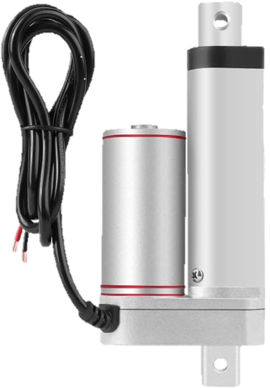
The Linear Motion Actuator (LMA) is a device designed to convert electrical energy into linear motion. This component is widely used in automation, robotics, and various industrial applications where precise linear movement is required. LMAs are essential in systems that require controlled and repeatable motion, such as CNC machines, 3D printers, and automated assembly lines.
Explore Projects Built with LMA
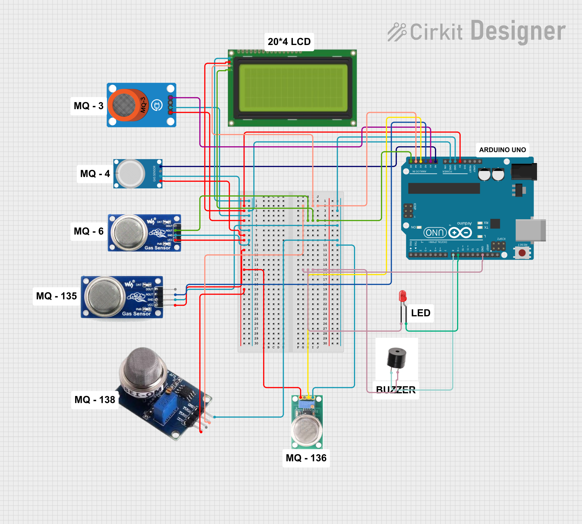
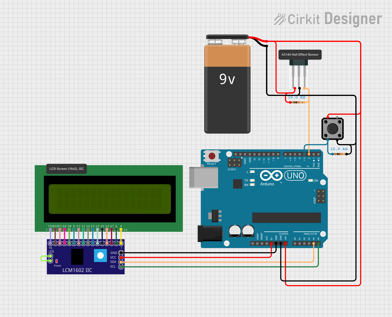
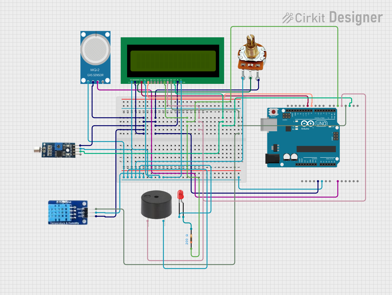
Explore Projects Built with LMA
Technical Specifications
Key Technical Details
| Parameter | Value |
|---|---|
| Operating Voltage | 12V - 24V DC |
| Current Rating | 1A - 5A |
| Stroke Length | 50mm - 300mm |
| Load Capacity | 10kg - 100kg |
| Speed | 5mm/s - 50mm/s |
| Position Feedback | Optional (Potentiometer) |
| Control Interface | PWM, Analog, or Digital |
| Operating Temperature | -10°C to 50°C |
Pin Configuration and Descriptions
| Pin Number | Pin Name | Description |
|---|---|---|
| 1 | VCC | Power Supply (12V - 24V DC) |
| 2 | GND | Ground |
| 3 | IN1 | Control Signal 1 (Direction/Speed Control) |
| 4 | IN2 | Control Signal 2 (Direction/Speed Control) |
| 5 | FB | Feedback Signal (Optional, for position sensing) |
Usage Instructions
How to Use the LMA in a Circuit
- Power Supply: Connect the VCC pin to a 12V - 24V DC power supply and the GND pin to the ground.
- Control Signals: Use IN1 and IN2 pins to control the direction and speed of the actuator. These can be connected to a microcontroller (e.g., Arduino) or a motor driver.
- Feedback Signal: If position feedback is required, connect the FB pin to an analog input on your microcontroller to read the position.
Important Considerations and Best Practices
- Power Supply: Ensure that the power supply can provide sufficient current for the actuator's operation.
- Heat Dissipation: LMAs can generate heat during operation. Ensure proper ventilation or heat sinking to avoid overheating.
- Load Capacity: Do not exceed the specified load capacity to prevent damage to the actuator.
- Control Signals: Use appropriate control signals (PWM, analog, or digital) as per the actuator's specifications.
Example: Connecting LMA to Arduino UNO
Circuit Diagram
Arduino UNO          LMA
-----------          ---
5V         --------> VCC
GND        --------> GND
D9         --------> IN1
D10        --------> IN2
A0         --------> FB (Optional)
Arduino Code
// Define pin connections
const int IN1 = 9;
const int IN2 = 10;
const int FB = A0; // Optional, for position feedback

void setup() {
  // Initialize pins as outputs
  pinMode(IN1, OUTPUT);
  pinMode(IN2, OUTPUT);
  pinMode(FB, INPUT); // Optional, for position feedback

  // Start with the actuator stopped
  digitalWrite(IN1, LOW);
  digitalWrite(IN2, LOW);
}

void loop() {
  // Example: Move actuator forward
  digitalWrite(IN1, HIGH);
  digitalWrite(IN2, LOW);
  delay(2000); // Move for 2 seconds

  // Stop actuator
  digitalWrite(IN1, LOW);
  digitalWrite(IN2, LOW);
  delay(1000); // Wait for 1 second

  // Example: Move actuator backward
  digitalWrite(IN1, LOW);
  digitalWrite(IN2, HIGH);
  delay(2000); // Move for 2 seconds

  // Stop actuator
  digitalWrite(IN1, LOW);
  digitalWrite(IN2, LOW);
  delay(1000); // Wait for 1 second

  // Optional: Read position feedback
  int position = analogRead(FB);
  // Use the position value as needed
}
Troubleshooting and FAQs
Common Issues
Actuator Not Moving:
- Solution: Check the power supply and ensure it is within the specified voltage range. Verify that control signals are correctly connected and functioning.
Overheating:
- Solution: Ensure proper ventilation and avoid exceeding the load capacity. Consider using a heat sink if necessary.
Inaccurate Position Feedback:
- Solution: Calibrate the feedback signal and ensure that the feedback pin is correctly connected to the microcontroller.
FAQs
Can I use an LMA with a different voltage range?
- It is recommended to use the LMA within the specified voltage range (12V - 24V DC) to ensure proper operation and avoid damage.
How do I control the speed of the LMA?
- The speed can be controlled using PWM signals on the control pins (IN1 and IN2). Adjust the duty cycle of the PWM signal to vary the speed.
Is it possible to get position feedback from the LMA?
- Yes, if the LMA is equipped with a position feedback mechanism (e.g., a potentiometer), you can read the feedback signal using an analog input on your microcontroller.
By following this documentation, users can effectively integrate and utilize the Linear Motion Actuator (LMA) in their projects, ensuring reliable and precise linear motion control.