How to Use USB 6009: Examples, Pinouts, and Specs
Introduction
The USB 6009, manufactured by National Instruments (Part ID: USB609), is a multifunction data acquisition (DAQ) device designed for seamless integration with computers via USB. It provides a versatile solution for measurement and control applications, offering analog input, analog output, digital I/O, and counter/timer functionalities. Its compact design and plug-and-play capability make it ideal for both laboratory and field use.
Explore Projects Built with USB 6009


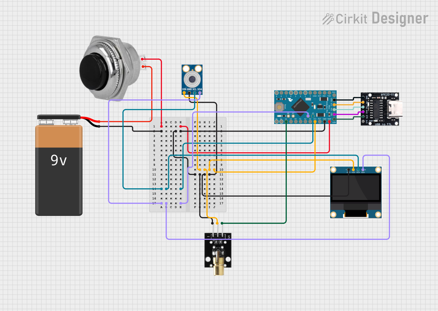
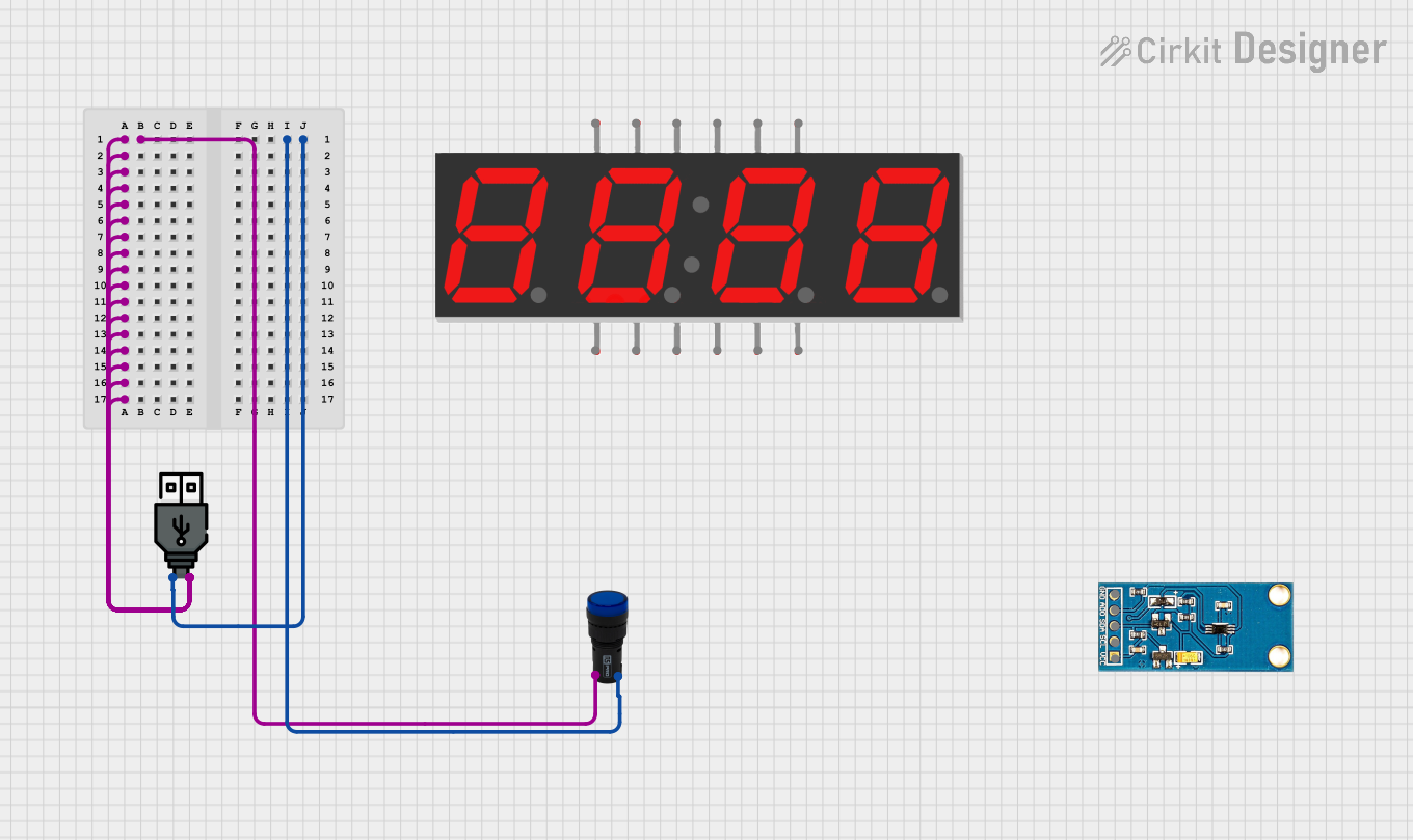
Explore Projects Built with USB 6009
Common Applications and Use Cases
- Sensor data acquisition (e.g., temperature, pressure, or voltage sensors)
- Signal generation and waveform output
- Digital control and monitoring of devices
- Prototyping and educational experiments
- Industrial automation and process control
Technical Specifications
Key Technical Details
| Parameter | Specification |
|---|---|
| Analog Input Channels | 8 single-ended or 4 differential |
| Analog Input Resolution | 14 bits |
| Analog Input Range | ±10 V, ±5 V, ±2 V, ±1 V |
| Analog Output Channels | 2 |
| Analog Output Resolution | 12 bits |
| Analog Output Range | 0–5 V |
| Digital I/O Channels | 12 (TTL logic levels) |
| Counter/Timer Channels | 1 (32-bit resolution) |
| Maximum Sampling Rate | 48 kS/s (aggregate for AI channels) |
| USB Interface | USB 2.0 |
| Power Supply | USB-powered |
| Operating Temperature Range | 0 °C to 55 °C |
| Dimensions | 88.9 mm × 63.5 mm × 20.32 mm |
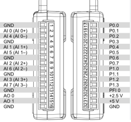
Pin Configuration and Descriptions
Analog Input Channels
| Pin Number | Signal Name | Description |
|---|---|---|
| AI0 | Analog In 0 | Single-ended or differential input |
| AI1 | Analog In 1 | Single-ended or differential input |
| AI2 | Analog In 2 | Single-ended or differential input |
| AI3 | Analog In 3 | Single-ended or differential input |
| AI4 | Analog In 4 | Single-ended input |
| AI5 | Analog In 5 | Single-ended input |
| AI6 | Analog In 6 | Single-ended input |
| AI7 | Analog In 7 | Single-ended input |
Analog Output Channels
| Pin Number | Signal Name | Description |
|---|---|---|
| AO0 | Analog Out 0 | Voltage output channel |
| AO1 | Analog Out 1 | Voltage output channel |
Digital I/O Channels
| Pin Number | Signal Name | Description |
|---|---|---|
| DIO0 | Digital I/O 0 | Configurable as input or output |
| DIO1 | Digital I/O 1 | Configurable as input or output |
| DIO2 | Digital I/O 2 | Configurable as input or output |
| DIO3 | Digital I/O 3 | Configurable as input or output |
| DIO4 | Digital I/O 4 | Configurable as input or output |
| DIO5 | Digital I/O 5 | Configurable as input or output |
| DIO6 | Digital I/O 6 | Configurable as input or output |
| DIO7 | Digital I/O 7 | Configurable as input or output |
| DIO8 | Digital I/O 8 | Configurable as input or output |
| DIO9 | Digital I/O 9 | Configurable as input or output |
| DIO10 | Digital I/O 10 | Configurable as input or output |
| DIO11 | Digital I/O 11 | Configurable as input or output |
Counter/Timer
| Pin Number | Signal Name | Description |
|---|---|---|
| CTR0 | Counter 0 | 32-bit counter/timer input |
Usage Instructions
How to Use the USB 6009 in a Circuit
- Connect the Device to a Computer: Plug the USB 6009 into a USB port on your computer. Ensure the appropriate drivers (NI-DAQmx) are installed.
- Configure the Device: Use National Instruments' software (e.g., LabVIEW or NI MAX) to configure the device, set up channels, and define input/output ranges.
- Connect Signals:
- For analog inputs, connect the signal source to the appropriate AI pins.
- For analog outputs, connect the load to the AO pins.
- For digital I/O, connect the device to the DIO pins as needed.
- Write and Execute Code: Use LabVIEW, Python (with NI-DAQmx library), or other supported programming environments to control the device and acquire data.
Important Considerations and Best Practices
- Grounding: Ensure proper grounding to avoid noise and signal interference.
- Input Voltage Limits: Do not exceed the specified input voltage range to prevent damage.
- Sampling Rate: Be mindful of the aggregate sampling rate when using multiple analog input channels.
- Cable Length: Use short, shielded cables to minimize noise and signal degradation.
- Power Supply: The device is USB-powered; ensure the USB port provides sufficient power.
Example Code for Arduino UNO Integration
While the USB 6009 is typically used with a computer, it can interface with an Arduino UNO via digital I/O. Below is an example of controlling a digital output pin on the USB 6009 using an Arduino:
// Example: Controlling a digital output pin on the USB 6009
// This code toggles a digital pin on the USB 6009 using an Arduino UNO.

const int usb6009Pin = 7; // Connect Arduino pin 7 to USB 6009 DIO0

void setup() {
  pinMode(usb6009Pin, OUTPUT); // Set pin as output
}

void loop() {
  digitalWrite(usb6009Pin, HIGH); // Set USB 6009 DIO0 to HIGH
  delay(1000); // Wait for 1 second
  digitalWrite(usb6009Pin, LOW);  // Set USB 6009 DIO0 to LOW
  delay(1000); // Wait for 1 second
}
Troubleshooting and FAQs
Common Issues and Solutions
Device Not Recognized by Computer:
- Ensure the USB cable is securely connected.
- Verify that the NI-DAQmx driver is installed and up to date.
- Try connecting to a different USB port or computer.
No Signal on Analog Output:
- Check the configuration in NI MAX or LabVIEW.
- Verify that the load is properly connected to the AO pins.
- Ensure the output range is correctly set.
Noise in Analog Input Signals:
- Use shielded cables and proper grounding.
- Reduce the sampling rate if high-frequency noise is present.
- Place the device away from sources of electromagnetic interference.
Digital I/O Not Responding:
- Confirm the pin direction (input/output) is correctly configured.
- Check the wiring and connections to external devices.
FAQs
Q: Can the USB 6009 be used with operating systems other than Windows?
A: Yes, the USB 6009 is compatible with Linux and macOS, but ensure the appropriate drivers and software are installed.
Q: What is the maximum cable length for USB connectivity?
A: The maximum recommended USB cable length is 5 meters to maintain reliable communication.
Q: Can the USB 6009 be powered externally?
A: No, the USB 6009 is designed to be powered solely through the USB connection.
Q: Is the USB 6009 suitable for high-speed data acquisition?
A: The USB 6009 is best suited for low- to medium-speed applications due to its 48 kS/s maximum sampling rate. For high-speed applications, consider other NI DAQ devices.