How to Use 24V DC Motor 30W 2.1 Amp 60 RPM: Examples, Pinouts, and Specs
Introduction
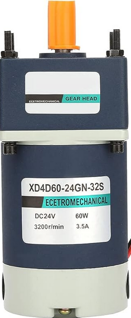
The 24V DC Motor (Model: XD3D30-24GN-32S), manufactured by NIX DA MOTOR Company CO., LTD, is a robust and efficient motor designed for a wide range of mechanical applications. This motor operates at 24 volts, delivers a power output of 30 watts, and has a current draw of 2.1 amps. With a rotational speed of 60 RPM, it is ideal for applications requiring precise and consistent low-speed torque.
Explore Projects Built with 24V DC Motor 30W 2.1 Amp 60 RPM


Explore Projects Built with 24V DC Motor 30W 2.1 Amp 60 RPM
Common Applications
- Conveyor belt systems
- Robotic arms and automation equipment
- Electric gates and doors
- Industrial machinery
- DIY projects requiring low-speed, high-torque motors
Technical Specifications
Key Specifications
| Parameter | Value |
|---|---|
| Manufacturer | NIX DA MOTOR Company CO., LTD |
| Model Number | XD3D30-24GN-32S |
| Rated Voltage | 24V DC |
| Rated Power | 30W |
| Rated Current | 2.1A |
| Rotational Speed | 60 RPM |
| Torque | 4.8 Nm (approx.) |
| Shaft Diameter | 8 mm |
| Motor Type | Brushed DC Motor |
| Operating Temperature | -10°C to 50°C |
| Weight | 1.2 kg |
Pin Configuration and Descriptions
The motor has two terminals for electrical connections:
| Pin/Terminal | Description |
|---|---|
| Terminal 1 | Positive terminal (+24V DC) |
| Terminal 2 | Negative terminal (Ground) |
Note: Ensure proper polarity when connecting the motor to avoid damage.
Usage Instructions
How to Use the Motor in a Circuit
- Power Supply: Use a regulated 24V DC power supply capable of delivering at least 2.5A to ensure stable operation.
- Polarity: Connect Terminal 1 to the positive terminal of the power supply and Terminal 2 to the ground.
- Motor Driver: For speed and direction control, use a motor driver or H-bridge circuit compatible with 24V DC motors.
- Load Connection: Attach the desired mechanical load to the motor shaft. Ensure the load does not exceed the motor's torque rating (4.8 Nm).
- Testing: Gradually apply power and monitor the motor's performance. Avoid sudden changes in voltage to prevent damage.
Important Considerations and Best Practices
- Overcurrent Protection: Use a fuse or circuit breaker rated at 2.5A to protect the motor from overcurrent conditions.
- Heat Dissipation: Ensure adequate ventilation around the motor to prevent overheating during prolonged use.
- Mounting: Secure the motor firmly to avoid vibrations that could affect performance.
- Reverse Polarity: Avoid reversing the polarity of the power supply, as it may damage the motor.
- PWM Control: For speed control, use a PWM (Pulse Width Modulation) signal with a motor driver.
Example: Controlling the Motor with an Arduino UNO
Below is an example of how to control the motor using an Arduino UNO and an L298N motor driver:
// Arduino code to control a 24V DC motor using an L298N motor driver

// Define motor control pins
const int IN1 = 9;  // IN1 pin on L298N for motor direction
const int IN2 = 8;  // IN2 pin on L298N for motor direction
const int ENA = 10; // ENA pin on L298N for motor speed (PWM)

// Setup function
void setup() {
  pinMode(IN1, OUTPUT); // Set IN1 as output
  pinMode(IN2, OUTPUT); // Set IN2 as output
  pinMode(ENA, OUTPUT); // Set ENA as output
}

// Loop function
void loop() {
  // Rotate motor in forward direction
  digitalWrite(IN1, HIGH); // Set IN1 high
  digitalWrite(IN2, LOW);  // Set IN2 low
  analogWrite(ENA, 128);   // Set motor speed to 50% (PWM value: 128)

  delay(5000); // Run motor for 5 seconds

  // Stop the motor
  digitalWrite(IN1, LOW);  // Set IN1 low
  digitalWrite(IN2, LOW);  // Set IN2 low
  analogWrite(ENA, 0);     // Set motor speed to 0

  delay(2000); // Wait for 2 seconds

  // Rotate motor in reverse direction
  digitalWrite(IN1, LOW);  // Set IN1 low
  digitalWrite(IN2, HIGH); // Set IN2 high
  analogWrite(ENA, 128);   // Set motor speed to 50% (PWM value: 128)

  delay(5000); // Run motor for 5 seconds

  // Stop the motor
  digitalWrite(IN1, LOW);  // Set IN1 low
  digitalWrite(IN2, LOW);  // Set IN2 low
  analogWrite(ENA, 0);     // Set motor speed to 0

  delay(2000); // Wait for 2 seconds
}
Note: Ensure the L298N motor driver is powered with a 24V DC supply and properly connected to the motor.
Troubleshooting and FAQs
Common Issues and Solutions
Motor Does Not Start
- Cause: Insufficient power supply or incorrect wiring.
- Solution: Verify the power supply voltage and current rating. Check the wiring for proper connections.
Motor Overheats
- Cause: Prolonged operation under excessive load or poor ventilation.
- Solution: Reduce the load on the motor and ensure proper ventilation.
Motor Runs in the Wrong Direction
- Cause: Reversed polarity of the power supply or control signals.
- Solution: Swap the connections of Terminal 1 and Terminal 2 or adjust the motor driver control signals.
Motor Vibrates Excessively
- Cause: Loose mounting or unbalanced load.
- Solution: Secure the motor firmly and ensure the load is balanced.
FAQs
Q: Can this motor be used with a battery?
- A: Yes, a 24V DC battery with sufficient current capacity (at least 2.5A) can be used.
Q: Is this motor compatible with PWM speed control?
- A: Yes, the motor can be controlled using PWM signals via a motor driver.
Q: Can the motor operate at voltages lower than 24V?
- A: While the motor may run at lower voltages, its performance (speed and torque) will be reduced.
Q: What is the maximum load this motor can handle?
- A: The motor can handle loads up to its rated torque of 4.8 Nm. Exceeding this may damage the motor.
This concludes the documentation for the 24V DC Motor 30W 2.1 Amp 60 RPM (Model: XD3D30-24GN-32S). For further assistance, refer to the manufacturer's datasheet or contact technical support.