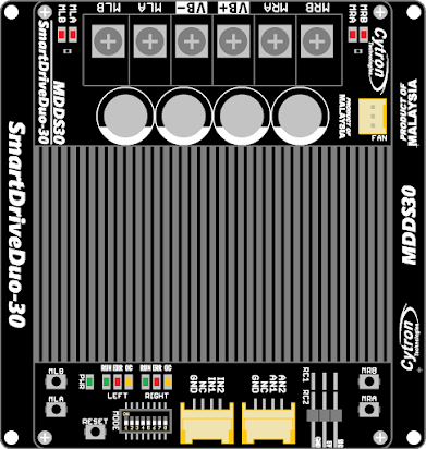
The MDDS30, manufactured by Cytron, is a high-performance digital signal processor (DSP) designed specifically for audio processing applications. It incorporates advanced algorithms for sound enhancement, noise reduction, and audio effects, making it an ideal choice for professional audio equipment, home theater systems, and consumer electronics. With its robust design and versatile functionality, the MDDS30 is widely used in applications requiring superior audio quality and real-time processing.
Explore Projects Built with MDDS30
Use Cirkit Designer to design, explore, and prototype these projects online. Some projects support real-time simulation. Click "Open Project" to start designing instantly!
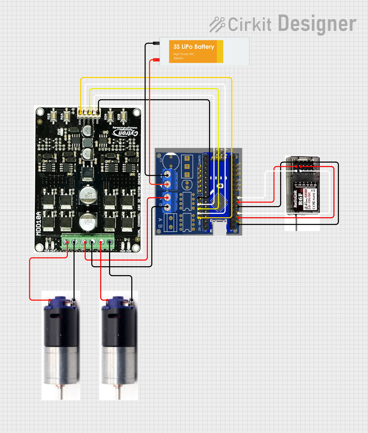
This circuit is a remote-controlled motor driver system powered by a LiPo battery. It uses a Massive RC MDEx microcontroller to control an MDD10A dual motor driver, which in turn drives two GM25 DC motors. The R6FG receiver receives remote control signals to manage the motor directions and speeds.
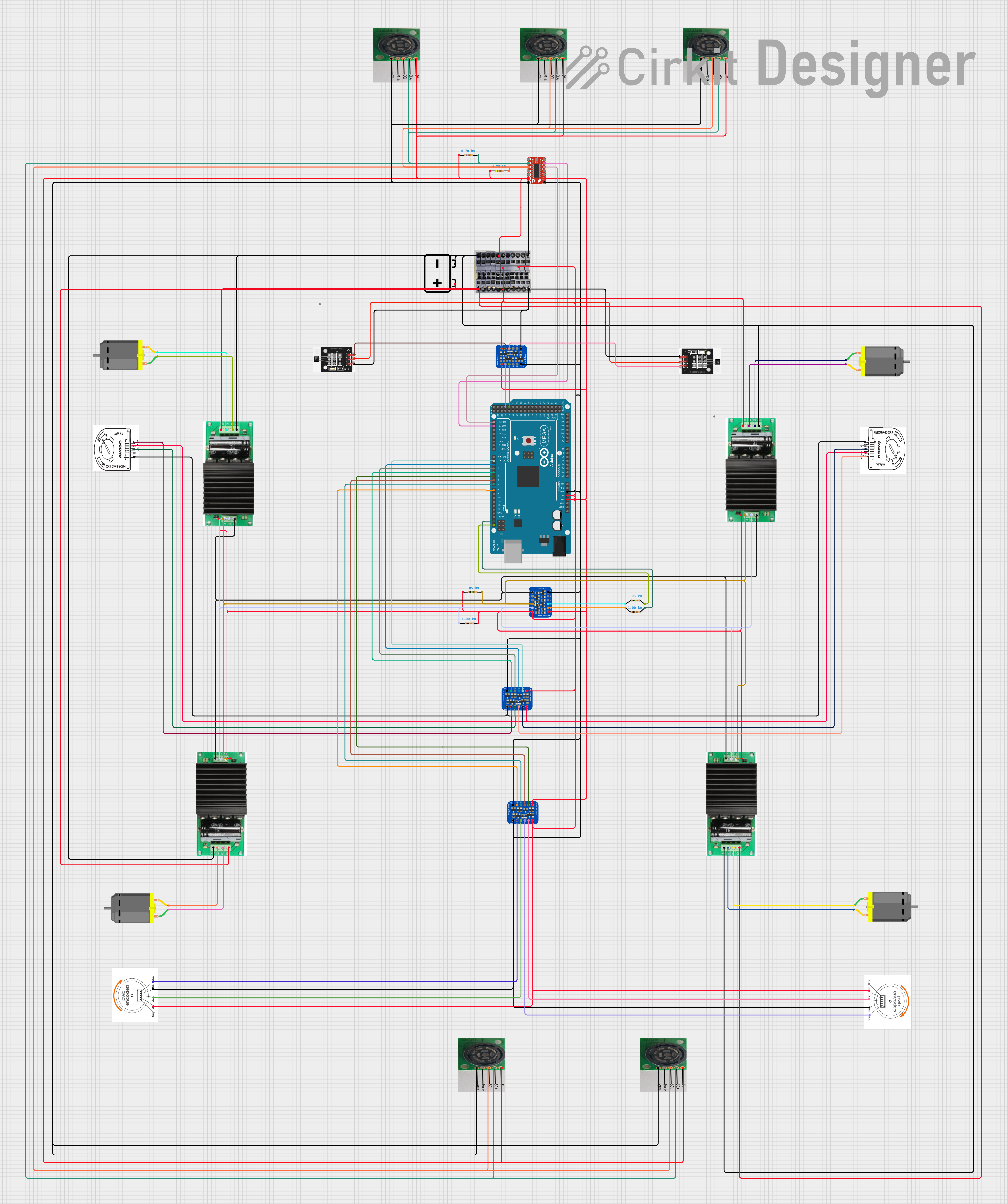
This is a motor control system with feedback and sensor integration. It uses an Arduino Mega 2560 to control MD03 motor drivers for DC motors, receives position and speed feedback from HEDS encoders and Hall sensors, and measures distance with SR02 ultrasonic sensors. Logic level converters ensure compatibility between different voltage levels of the components.
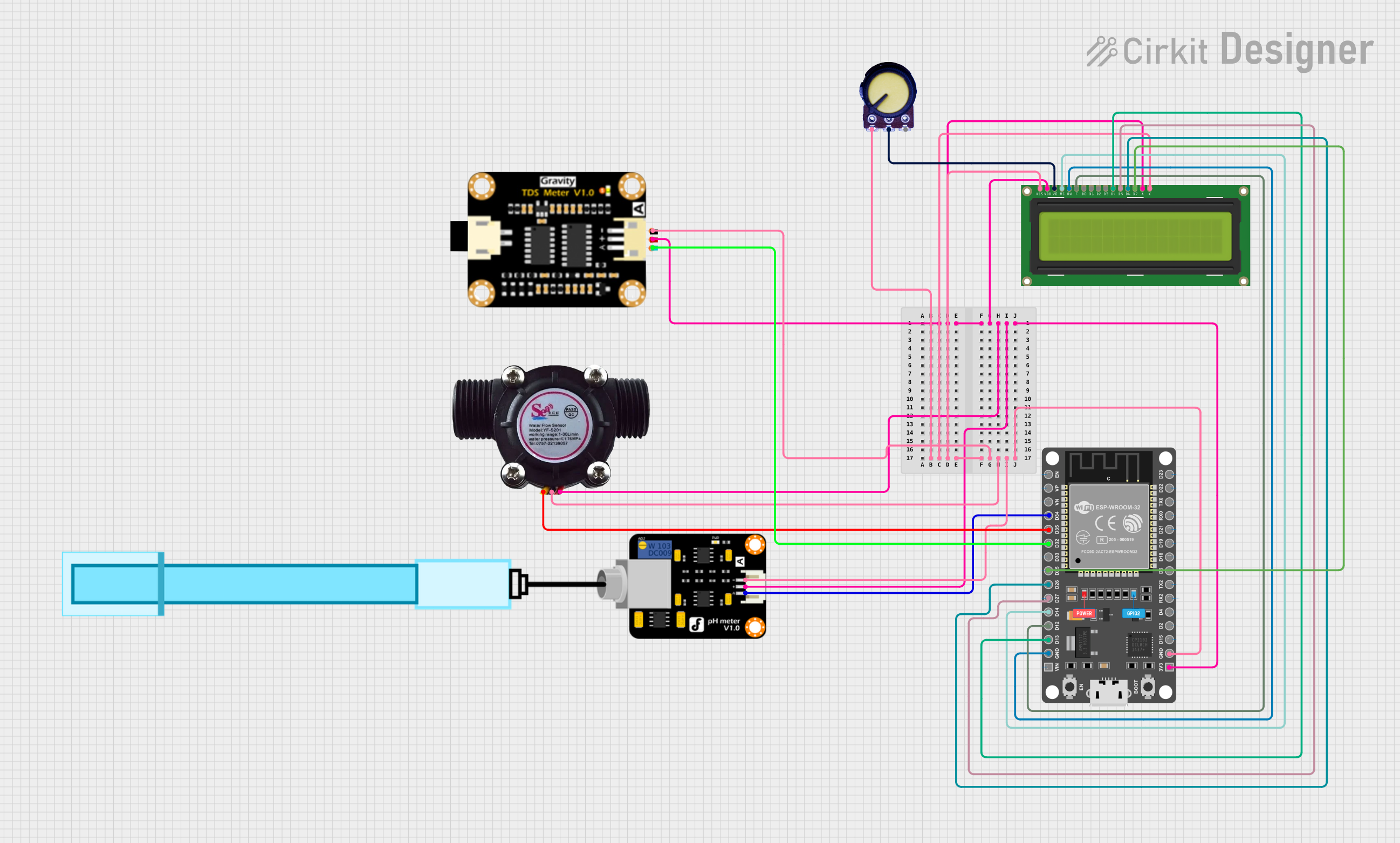
This circuit features an ESP32 microcontroller connected to a PH Meter, a water flow sensor, and a TDS (Total Dissolved Solids) sensor module for monitoring water quality. The ESP32 reads the sensor outputs and displays relevant data on a 16x2 LCD display. A potentiometer is used to adjust the contrast of the LCD, and all components are powered by the ESP32's 3.3V output, with common ground connections.
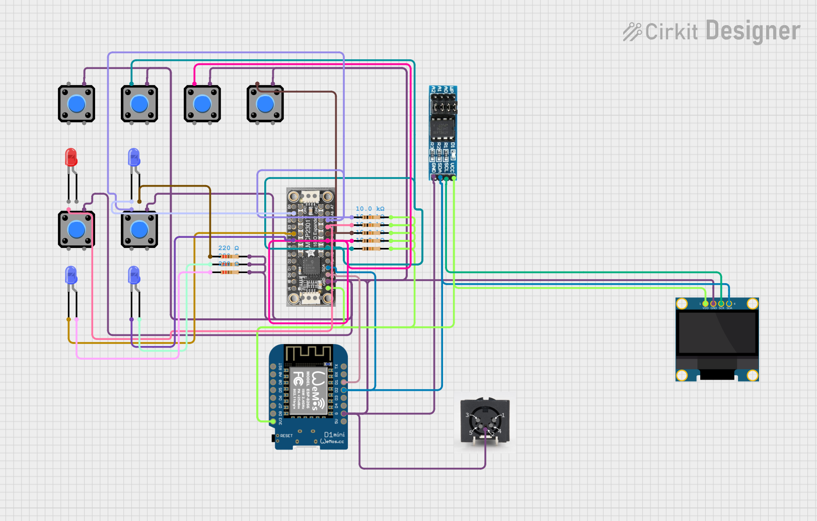
This is a microcontroller-based interactive device featuring a Wemos D1 Mini, an OLED display, external EEPROM, and an I/O expander. It includes user input buttons and status LEDs, with potential MIDI interface capabilities.
The MDDS30 is engineered to deliver exceptional performance in audio processing. Below are its key technical specifications:
General Specifications
Parameter
Value
Manufacturer
Cytron
Processor Type
Digital Signal Processor (DSP)
Operating Voltage
3.3V to 5V
Power Consumption
1.2W (typical)
Clock Speed
200 MHz
Audio Channels Supported
Up to 8 channels
Audio Resolution
24-bit
Sampling Rate
Up to 192 kHz
Communication Interface
I2C, SPI, UART
Package Type
QFP-64
Pin Configuration
The MDDS30 features a 64-pin QFP (Quad Flat Package) layout. Below is a summary of the pin configuration:
Pin Number
Pin Name
Description
1
VDD
Power supply (3.3V to 5V)
2
GND
Ground
3
I2C_SCL
I2C clock line
4
I2C_SDA
I2C data line
5
SPI_MOSI
SPI Master Out Slave In
6
SPI_MISO
SPI Master In Slave Out
7
SPI_SCK
SPI clock
8
UART_TX
UART transmit
9
UART_RX
UART receive
10
AUDIO_IN1
Audio input channel 1
11
AUDIO_IN2
Audio input channel 2
12
AUDIO_OUT1
Audio output channel 1
13
AUDIO_OUT2
Audio output channel 2
14-64
Reserved
Reserved for additional functionality
Usage Instructions
The MDDS30 is designed to be integrated into audio processing circuits. Below are the steps and best practices for using the component:
Basic Circuit Integration
Power Supply: Connect the VDD pin to a stable 3.3V or 5V power source and the GND pin to ground.
Audio Input/Output: Connect audio input signals to the AUDIO_IN pins and retrieve processed audio from the AUDIO_OUT pins.
Communication Interface: Use I2C, SPI, or UART to configure the DSP and control its functionality. Ensure proper pull-up resistors for I2C lines if required.
Clock Signal: Provide an external clock signal if necessary, or configure the internal clock.
Important Considerations
Decoupling Capacitors: Place decoupling capacitors (e.g., 0.1 µF) near the VDD pin to reduce noise and ensure stable operation.
Heat Dissipation: Ensure adequate heat dissipation, as the DSP may generate heat during operation.
Signal Integrity: Use shielded cables for audio signals to minimize interference and maintain audio quality.
Firmware Updates: Regularly update the firmware to access the latest audio processing algorithms and features.
Example: Connecting MDDS30 to Arduino UNO
The MDDS30 can be controlled using an Arduino UNO via the I2C interface. Below is an example code snippet:
#include <Wire.h> // Include the Wire library for I2C communication

#define MDDS30_I2C_ADDRESS 0x40 // Replace with the actual I2C address of MDDS30

void setup() {
  Wire.begin(); // Initialize I2C communication
  Serial.begin(9600); // Initialize serial communication for debugging

  // Send initialization commands to MDDS30
  Wire.beginTransmission(MDDS30_I2C_ADDRESS);
  Wire.write(0x01); // Example command to initialize the DSP
  Wire.endTransmission();

  Serial.println("MDDS30 initialized.");
}

void loop() {
  // Example: Send a command to adjust audio settings
  Wire.beginTransmission(MDDS30_I2C_ADDRESS);
  Wire.write(0x02); // Example command to adjust audio settings
  Wire.write(0x10); // Example parameter value
  Wire.endTransmission();

  delay(1000); // Wait for 1 second before sending the next command
}
Notes:
Replace 0x40 with the actual I2C address of your MDDS30.
Refer to the MDDS30 datasheet for a complete list of commands and parameters.
Troubleshooting and FAQs
Common Issues and Solutions
No Audio Output
Cause: Incorrect wiring or configuration.
Solution: Verify connections to AUDIO_IN and AUDIO_OUT pins. Check the DSP configuration via the communication interface.
Distorted Audio
Cause: Signal interference or incorrect sampling rate.
Solution: Use shielded cables for audio signals and ensure the sampling rate matches the input source.
Communication Failure
Cause: Incorrect I2C/SPI/UART settings.
Solution: Double-check the communication protocol settings (e.g., baud rate, clock speed) and ensure proper pull-up resistors for I2C lines.
Overheating
Cause: Insufficient heat dissipation.
Solution: Add a heat sink or improve ventilation around the DSP.
FAQs
Q: Can the MDDS30 process multiple audio channels simultaneously?
A: Yes, the MDDS30 supports up to 8 audio channels for simultaneous processing.
Q: What is the maximum sampling rate supported by the MDDS30?
A: The MDDS30 supports a maximum sampling rate of 192 kHz.
Q: Can I use the MDDS30 with a 5V microcontroller?
A: Yes, the MDDS30 operates within a voltage range of 3.3V to 5V, making it compatible with 5V microcontrollers.
Q: Does the MDDS30 require external memory?
A: No, the MDDS30 has built-in memory for most applications. However, external memory can be added for advanced use cases.
By following this documentation, users can effectively integrate and utilize the MDDS30 in their audio processing projects.

 Open Project in Cirkit Designer