How to Use Adafruit OLED Color 0.96 inch 96x64 w microSD: Examples, Pinouts, and Specs
Introduction
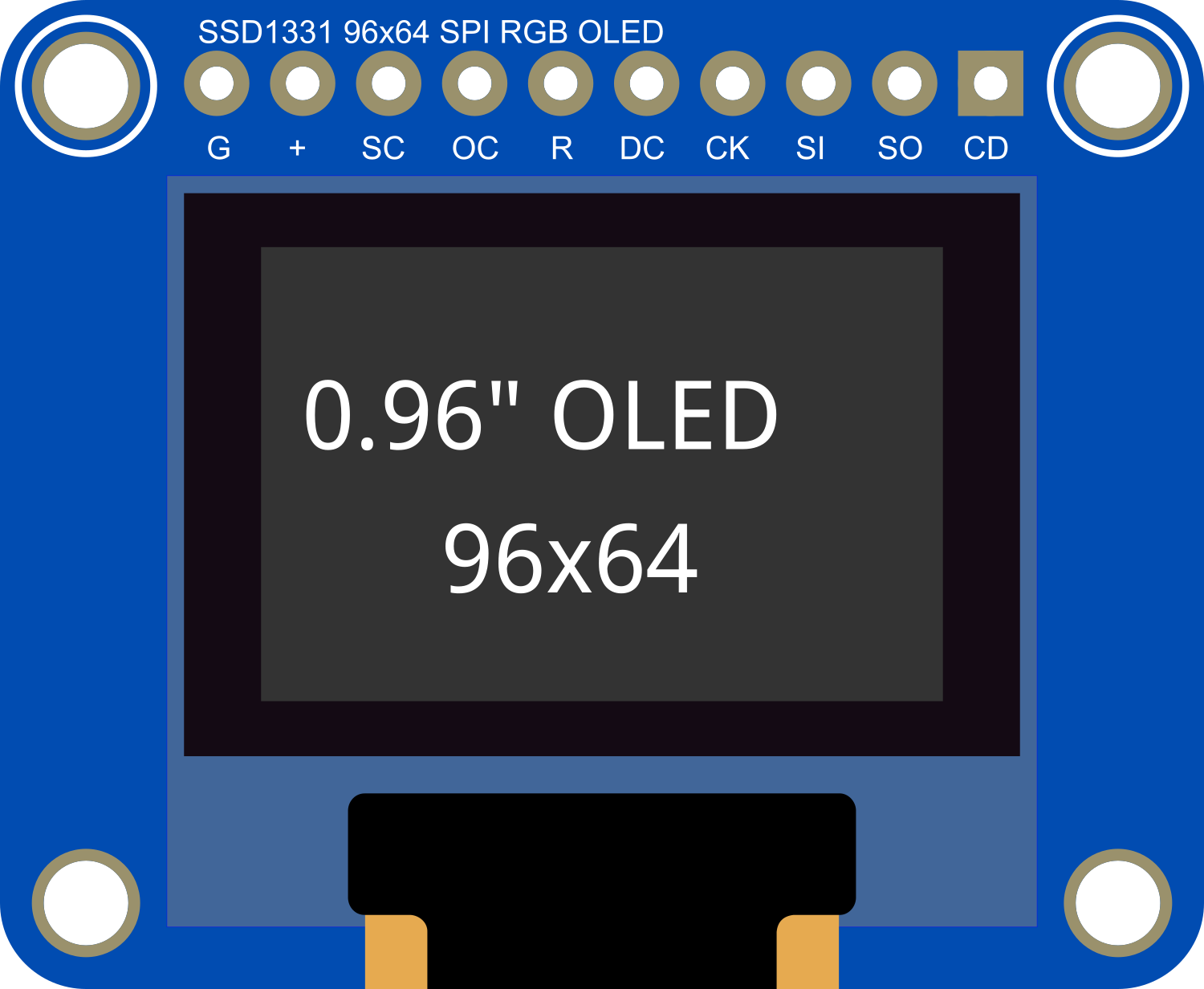
The Adafruit OLED Color 0.96 inch 96x64 with microSD is a compact and vibrant display module suitable for adding visual output to your electronics projects. This OLED (Organic Light Emitting Diode) display boasts a 96x64 pixel resolution with full-color capabilities, making it ideal for displaying graphics, images, and custom user interfaces. The inclusion of a microSD card slot allows for expanded storage options, enabling the display of images and data files directly from a microSD card.
Explore Projects Built with Adafruit OLED Color 0.96 inch 96x64 w microSD


Explore Projects Built with Adafruit OLED Color 0.96 inch 96x64 w microSD
Common Applications and Use Cases
- Wearable devices
- Portable instruments
- User interfaces for small-scale projects
- Data visualization for sensors
- Custom clocks and timers
Technical Specifications
Key Technical Details
- Display Type: OLED
- Screen Size: 0.96 inches diagonal
- Resolution: 96x64 pixels
- Color Depth: 16-bit color
- Interface: SPI/I2C
- Operating Voltage: 3.3V - 5V
- Logic Level: 3.3V (5V tolerant)
Pin Configuration and Descriptions
| Pin Number | Pin Name | Description |
|---|---|---|
| 1 | GND | Ground |
| 2 | VCC | Power supply (3.3V - 5V) |
| 3 | SCL | Serial Clock Line (SPI/I2C clock) |
| 4 | SDA | Serial Data Line (SPI/I2C data) |
| 5 | RES | Reset pin |
| 6 | DC | Data/Command control pin (SPI mode only) |
| 7 | CS | Chip Select (SPI mode only) |
| 8 | SD_CS | microSD card Chip Select |
Usage Instructions
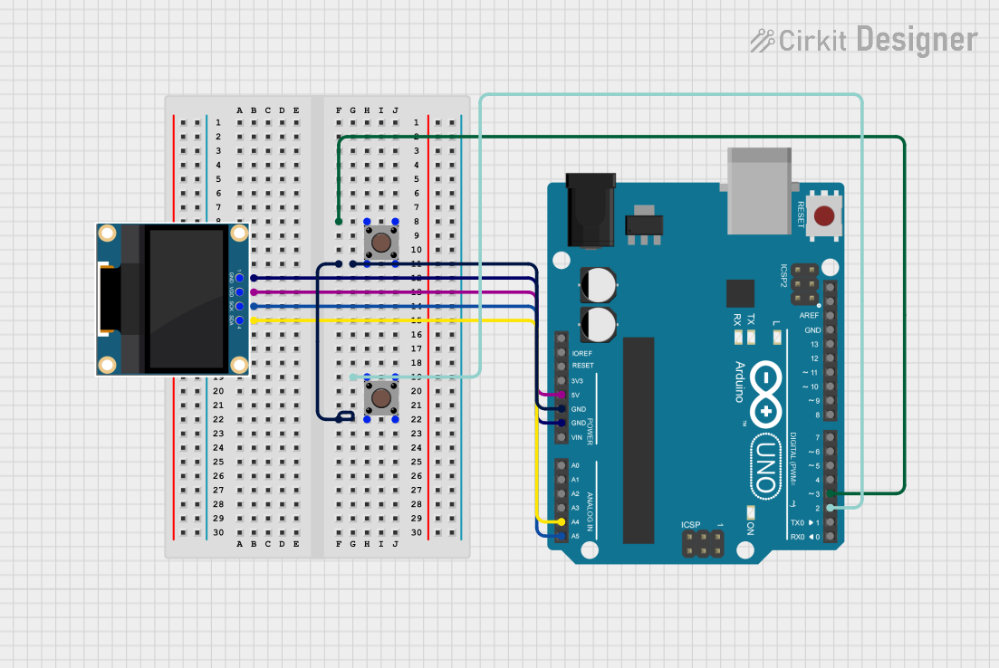
How to Use the Component in a Circuit
- Power Connections: Connect the VCC pin to a 3.3V or 5V power supply and the GND pin to the ground of your system.
- Data Connections: For SPI mode, connect SCL, SDA, RES, DC, and CS to the corresponding pins on your microcontroller. For I2C mode, only SCL and SDA are required.
- microSD Slot: Insert a formatted microSD card into the slot if you intend to use the onboard storage for displaying images.
Important Considerations and Best Practices
- Always ensure that the power supply is within the specified voltage range to prevent damage.
- Use level shifters if you are interfacing with a microcontroller that operates at a different logic level than the display.
- When using SPI mode, ensure that the CS pin is correctly managed to avoid conflicts with other SPI devices on the same bus.
- For optimal performance, use a high-quality, branded microSD card formatted to FAT16 or FAT32.
Example Code for Arduino UNO
#include <Adafruit_GFX.h>    // Include core graphics library for the display
#include <Adafruit_SSD1331.h> // Include the OLED driver library

// Pin definitions for the Arduino UNO
#define sclk 13
#define mosi 11
#define cs   10
#define rst  9
#define dc   8

// Create an Adafruit_SSD1331 object
Adafruit_SSD1331 display = Adafruit_SSD1331(cs, dc, mosi, sclk, rst);

void setup() {
  display.begin(); // Initialize the display
  display.fillScreen(BLACK); // Clear the screen to black
}

void loop() {
  // Example: Draw a red rectangle
  display.drawRect(10, 10, 50, 40, RED);
  delay(500);
  // Example: Fill the rectangle with blue color
  display.fillRect(10, 10, 50, 40, BLUE);
  delay(500);
}
Note: This example assumes that the display is connected in SPI mode. Make sure to install the Adafruit GFX and SSD1331 libraries before uploading the code to your Arduino UNO.
Troubleshooting and FAQs
Common Issues Users Might Face
- Display Not Powering On: Check the power connections and ensure the voltage is within the specified range.
- No Image Displayed: Verify that the SPI/I2C connections are correct and that the correct communication protocol is selected in your code.
- Corrupted Images: Ensure that the microSD card is properly formatted and that the image files are not corrupted.
Solutions and Tips for Troubleshooting
- Double-check wiring against the pin configuration table.
- Use example sketches from the Adafruit libraries to test basic functionality.
- If using SPI, ensure that other SPI devices are not interfering with the display's operation.
FAQs
Q: Can I power the display with 5V? A: Yes, the display can be powered with a 5V supply, but the logic level for data pins is 3.3V.
Q: How do I store images on the microSD card for the display? A: Images should be stored in a compatible format (e.g., BMP) and the card should be formatted to FAT16 or FAT32.
Q: Can I use this display with other microcontrollers besides Arduino UNO? A: Yes, the display can be used with any microcontroller that supports SPI or I2C communication, provided you adapt the pin connections and logic levels accordingly.