
How to Use SPH0645LM4H MEMS I2S Microphone: Examples, Pinouts, and Specs
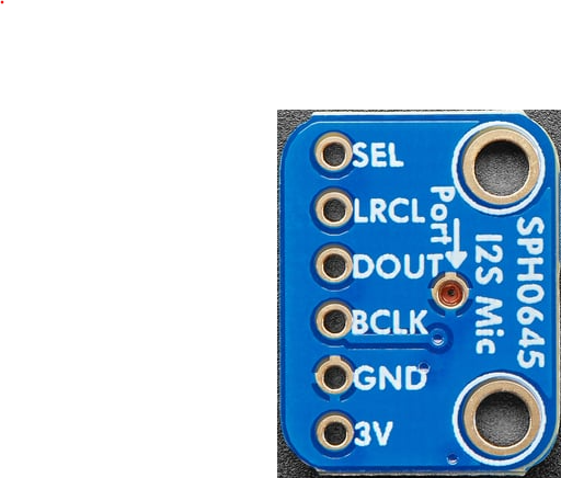
 Design with SPH0645LM4H MEMS I2S Microphone in Cirkit Designer
Introduction
The SPH0645LM4H MEMS I2S Microphone, manufactured by Adafruit (Part ID: 3421), is a digital microphone that uses the I2S (Inter-IC Sound) interface for audio data transmission. This microphone is designed for high-quality sound capture with low power consumption, making it an excellent choice for portable devices, voice recognition systems, and audio recording applications. Its compact size and digital output eliminate the need for analog-to-digital conversion, simplifying integration into modern electronics.
Explore Projects Built with SPH0645LM4H MEMS I2S Microphone
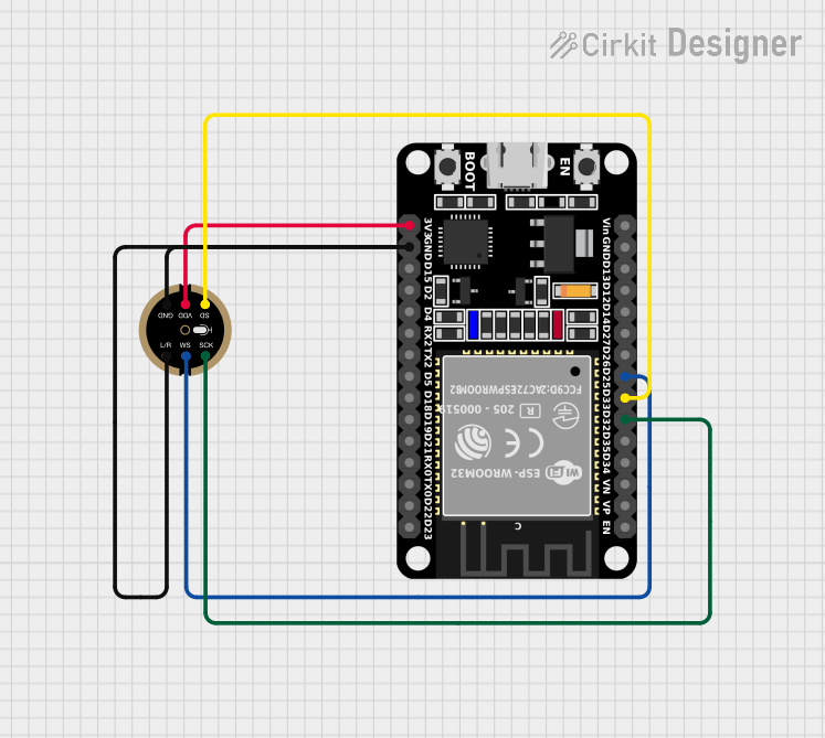 Open Project in Cirkit Designer
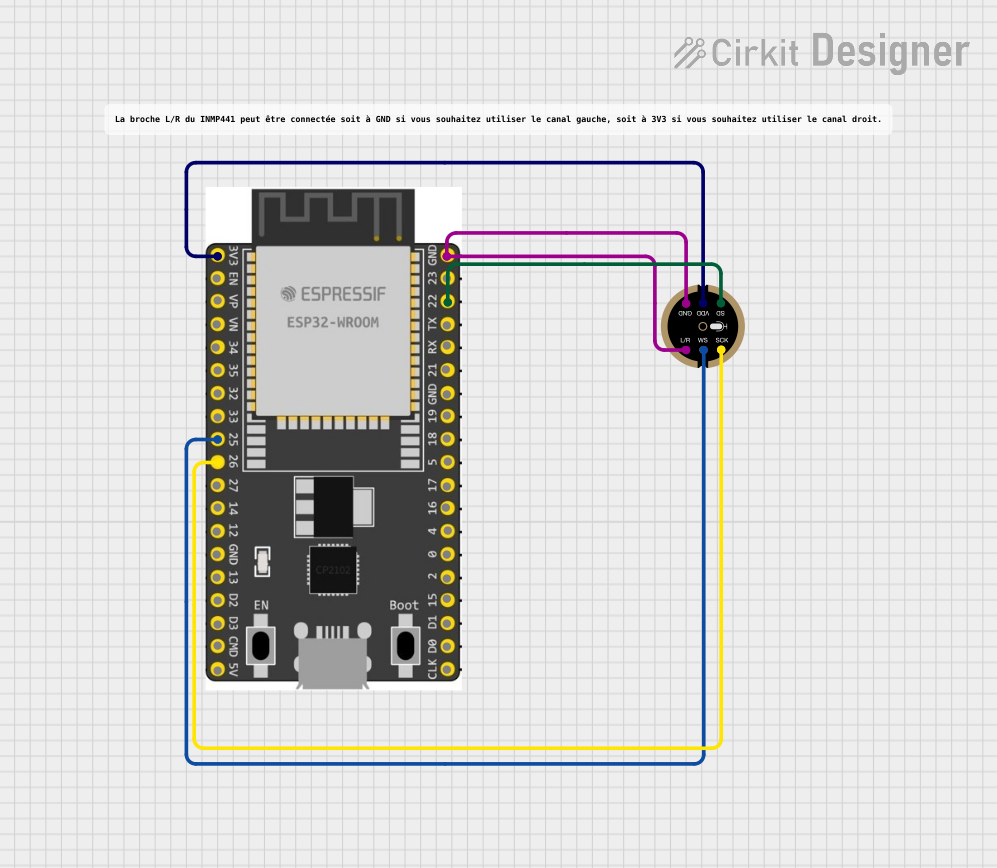 Open Project in Cirkit Designer
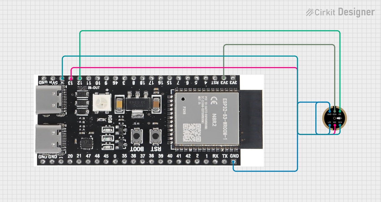 Open Project in Cirkit Designer
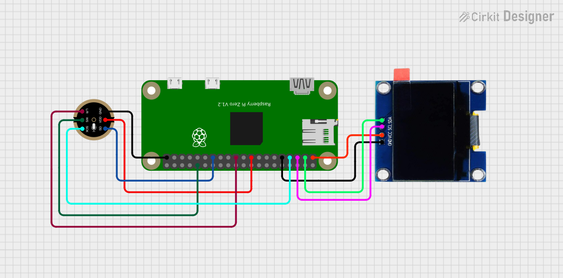 Open Project in Cirkit Designer
Explore Projects Built with SPH0645LM4H MEMS I2S Microphone
Open Project in Cirkit DesignerOpen Project in Cirkit DesignerOpen Project in Cirkit DesignerOpen Project in Cirkit DesignerCommon Applications
- Voice recognition systems (e.g., smart assistants)
- Audio recording and streaming devices
- Portable electronics (e.g., smartphones, tablets)
- Noise-canceling systems
- IoT devices with sound detection capabilities
Technical Specifications
Below are the key technical details of the SPH0645LM4H MEMS I2S Microphone:
| Parameter | Value |
|---|---|
| Supply Voltage (Vdd) | 1.8V to 3.3V |
| Current Consumption | 1.4 mA (typical) |
| Signal-to-Noise Ratio (SNR) | 65 dB |
| Frequency Response | 50 Hz to 15 kHz |
| Sensitivity | -26 dBFS ±3 dB |
| Output Format | I2S (Pulse Code Modulation) |
| Directionality | Omnidirectional |
| Operating Temperature | -40°C to +85°C |
| Dimensions | 3.5 mm x 2.65 mm x 0.98 mm |
Pin Configuration and Descriptions
The SPH0645LM4H MEMS I2S Microphone has 5 pins, as described in the table below:
| Pin Name | Pin Type | Description |
|---|---|---|
| VDD | Power | Power supply pin. Connect to a 1.8V to 3.3V power source. |
| GND | Ground | Ground pin. Connect to the ground of the circuit. |
| WS | Input | Word Select pin. Determines left or right channel for I2S data. |
| CLK | Input | Clock input for I2S communication. Connect to the I2S clock source. |
| DATA | Output | Digital audio data output. Connect to the I2S data input of the microcontroller. |
Usage Instructions
How to Use the SPH0645LM4H in a Circuit
- Power Supply: Connect the VDD pin to a 1.8V to 3.3V power source and the GND pin to the circuit ground.
- I2S Interface:
- Connect the
CLKpin to the I2S clock signal from your microcontroller. - Connect the
WSpin to the I2S word select signal. This pin determines whether the microphone outputs data for the left or right audio channel. - Connect the
DATApin to the I2S data input pin of your microcontroller.
- Connect the
- Bypass Capacitor: Place a 0.1 µF decoupling capacitor close to the VDD pin to stabilize the power supply.
- Microcontroller Configuration: Configure your microcontroller's I2S peripheral to match the microphone's output format (e.g., 16-bit data, 48 kHz sampling rate).
Important Considerations
- Clock Signal: Ensure the I2S clock signal is stable and within the microphone's supported range.
- Channel Selection: Use the
WSpin to select the desired audio channel (left or right). Tie it to GND for the left channel or VDD for the right channel. - PCB Layout: Keep the traces for the I2S signals (CLK, WS, DATA) as short as possible to minimize noise and signal degradation.
Example Code for Arduino UNO
The SPH0645LM4H is commonly used with microcontrollers like the Arduino. Below is an example of how to configure and read data from the microphone using an Arduino-compatible board with I2S support (e.g., ESP32):
#include <I2S.h> // Include the I2S library for ESP32 or compatible boards

void setup() {
  Serial.begin(115200); // Initialize serial communication for debugging

  // Initialize I2S with the microphone's configuration
  if (!I2S.begin(I2S_PHILIPS_MODE, 48000, 16)) {
    Serial.println("Failed to initialize I2S!");
    while (1); // Halt execution if I2S initialization fails
  }

  Serial.println("I2S initialized successfully!");
}

void loop() {
  int32_t sample = 0;

  // Read audio data from the microphone
  if (I2S.read((uint8_t *)&sample, sizeof(sample)) > 0) {
    // Convert the 32-bit sample to 16-bit for processing
    int16_t audioSample = sample >> 16;

    // Print the audio sample to the serial monitor
    Serial.println(audioSample);
  }
}
Notes:
- This example assumes the use of an ESP32 or another microcontroller with native I2S support. The Arduino UNO does not have built-in I2S capabilities, so an external I2S interface would be required.
Troubleshooting and FAQs
Common Issues
No Audio Data Output
- Cause: Incorrect I2S configuration or missing clock signal.
- Solution: Verify the I2S settings (e.g., sampling rate, bit depth) and ensure the
CLKpin is receiving a stable clock signal.
Distorted Audio
- Cause: Noise in the power supply or long signal traces.
- Solution: Add a decoupling capacitor near the VDD pin and minimize the length of I2S signal traces.
Microphone Not Responding
- Cause: Incorrect power supply voltage.
- Solution: Ensure the VDD pin is supplied with a voltage between 1.8V and 3.3V.
FAQs
Q: Can I use the SPH0645LM4H with a 5V microcontroller?
A: The microphone operates at 1.8V to 3.3V. If your microcontroller operates at 5V, use a level shifter for the I2S signals to avoid damaging the microphone.
Q: How do I select the audio channel (left or right)?
A: Use the WS pin. Tie it to GND for the left channel or VDD for the right channel.
Q: What is the maximum sampling rate supported by the microphone?
A: The SPH0645LM4H supports sampling rates up to 48 kHz.
Q: Can I use multiple microphones in a single system?
A: Yes, you can use multiple microphones by configuring their WS pins to output data on different channels (left or right).