How to Use Audio Level Meter: Examples, Pinouts, and Specs
Introduction
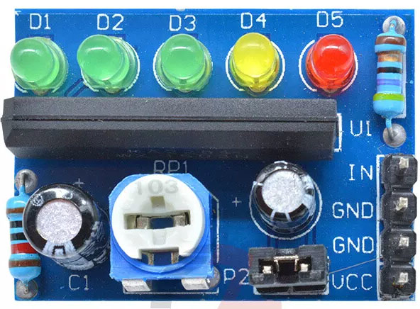
The KA2284 Audio Level Meter is an integrated circuit that provides a visual representation of the strength of an audio signal. It is commonly used in audio equipment, sound mixers, amplifiers, and various consumer electronics to display the audio level through a series of LED lights or a meter display. The KA2284 is particularly popular for its simplicity and ease of use, making it suitable for both hobbyist projects and professional applications.
Explore Projects Built with Audio Level Meter
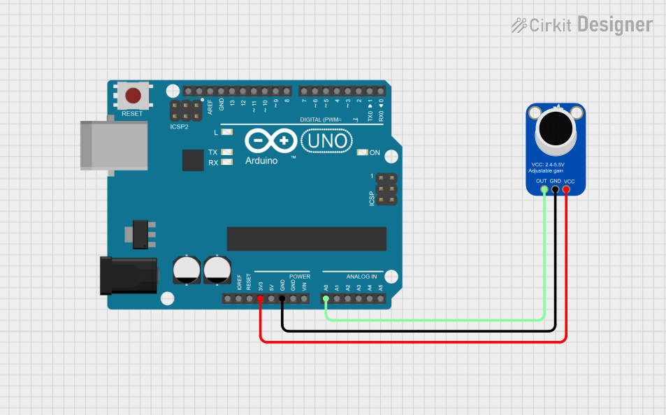
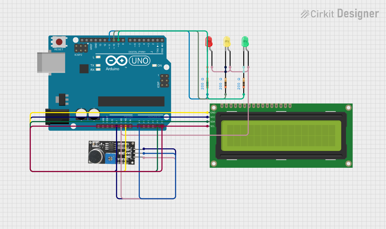
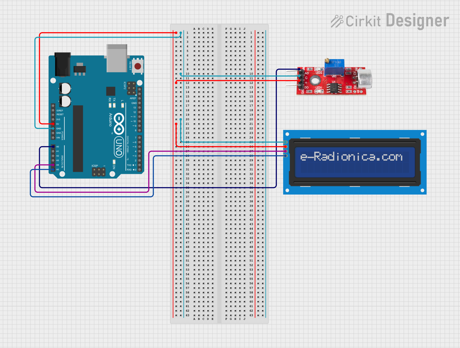

Explore Projects Built with Audio Level Meter
Technical Specifications
Key Technical Details
- Supply Voltage (Vcc): 3.5V to 12V
- Operating Current (Icc): 3.5mA to 7mA (Typical)
- Input Voltage Range (Vin): 150mV to 1.5V (peak-to-peak)
- Output: 5 LED indicators for level meter
- Frequency Response: 20Hz to 15kHz
Pin Configuration and Descriptions
| Pin Number | Name | Description |
|---|---|---|
| 1 | Vcc | Power supply input (3.5V to 12V) |
| 2 | GND | Ground connection |
| 3 | IN | Audio input signal |
| 4 | OUT | Audio output signal (if needed) |
| 5 | LED1 | Output to LED1 (lowest level) |
| 6 | LED2 | Output to LED2 |
| 7 | LED3 | Output to LED3 |
| 8 | LED4 | Output to LED4 |
| 9 | LED5 | Output to LED5 (highest level) |
| 10 | REF | Reference voltage adjustment (connect to GND with a resistor) |
Usage Instructions
How to Use the KA2284 in a Circuit
Power Supply: Connect the Vcc pin to a power supply between 3.5V and 12V. Ensure that the power supply is stable and within the specified range to avoid damaging the IC.
Ground Connection: Connect the GND pin to the ground of your power supply.
Audio Input: Connect the IN pin to the audio source you wish to measure. This could be an output from an amplifier, a mixer, or any audio-producing device.
LED Outputs: Connect each LED pin (LED1 to LED5) to an LED with an appropriate current-limiting resistor in series. The value of the resistor will depend on your supply voltage and the LED specifications.
Reference Voltage Adjustment: The REF pin can be connected to ground through a variable resistor (potentiometer) to set the reference voltage, which determines the threshold for lighting up the LEDs. Adjust this to calibrate the sensitivity of the audio level meter.
Important Considerations and Best Practices
- Ensure that the input audio signal does not exceed the maximum voltage rating to prevent damage to the IC.
- Use a decoupling capacitor (typically 0.1uF to 10uF) between Vcc and GND close to the IC to filter out noise and stabilize the power supply.
- If the audio source has a different ground reference, use a coupling capacitor in series with the input to avoid ground loops.
Troubleshooting and FAQs
Common Issues
- LEDs Not Lighting Up: Check the power supply and connections. Ensure that the LEDs are correctly oriented and that the current-limiting resistors are of the right value.
- LEDs Always On: The reference voltage may be set too low. Adjust the potentiometer connected to the REF pin to increase the threshold.
- Inaccurate Level Display: Ensure that the input signal is within the specified range and that the REF voltage is correctly adjusted.
Solutions and Tips
- If the LEDs are too dim or too bright, adjust the value of the current-limiting resistors.
- Use shielded cables for the audio input to reduce noise pickup.
- Place the KA2284 away from high-power components to avoid electromagnetic interference.
FAQs
Q: Can I use the KA2284 with a mono or stereo signal? A: The KA2284 is designed for mono signals. For stereo signals, you will need two KA2284 ICs, one for each channel.
Q: What is the purpose of the OUT pin? A: The OUT pin provides the option to daisy-chain the audio signal to another device or component without needing a separate splitter.
Q: How do I adjust the sensitivity of the audio level meter? A: Sensitivity can be adjusted by changing the resistance connected to the REF pin. A lower resistance will make the meter more sensitive, while a higher resistance will make it less sensitive.
Q: Can the KA2284 be used with an Arduino UNO? A: Yes, the KA2284 can be used with an Arduino UNO to create a digital audio level meter. You would read the state of the LED outputs with digital input pins on the Arduino.
Example Arduino Code
// Define the KA2284 LED output pins connected to the Arduino
const int ledPins[] = {2, 3, 4, 5, 6}; // LED1 to LED5 connected to digital pins 2 to 6

void setup() {
  // Set all the LED pins as input
  for (int i = 0; i < 5; i++) {
    pinMode(ledPins[i], INPUT);
  }
  Serial.begin(9600);
}

void loop() {
  // Read the state of each LED and print it to the serial monitor
  for (int i = 0; i < 5; i++) {
    int ledState = digitalRead(ledPins[i]);
    Serial.print("LED");
    Serial.print(i + 1);
    Serial.print(": ");
    Serial.println(ledState);
  }
  delay(500); // Delay for half a second
}
This code snippet demonstrates how to read the state of the LEDs connected to the KA2284 using an Arduino UNO. The states are printed to the serial monitor, which can be used to visualize the audio level on a computer.