Cirkit Designer Logo
Cirkit Designer
Your all-in-one circuit design IDE
Home / 
Component Documentation

How to Use ACS712 AC Current Sensor: Examples, Pinouts, and Specs

Image of ACS712 AC Current Sensor
Cirkit Designer LogoDesign with ACS712 AC Current Sensor in Cirkit Designer

Introduction

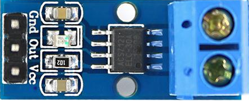
The ACS712 is a Hall effect-based linear current sensor designed to measure both AC and DC currents. It provides an analog voltage output proportional to the current flowing through the sensor. The device is compact, easy to use, and highly accurate, making it ideal for a wide range of applications.

Explore Projects Built with ACS712 AC Current Sensor

Use Cirkit Designer to design, explore, and prototype these projects online. Some projects support real-time simulation. Click "Open Project" to start designing instantly!
Wemos S2 Mini Controlled Smart Device with OLED Display, Thermal Printing, and RGB LED Strip
Image of DT NEA - Noah Patel: A project utilizing ACS712 AC Current Sensor in a practical application
This circuit features a Wemos S2 Mini microcontroller that controls a WS2812 RGB LED strip and communicates with a 0.96" OLED display and a 58mm mini thermal printer. The ACS712 Current Sensor is interfaced with the microcontroller to monitor current, and power is managed by a CD42 BMS connected to two 18650 Li-ion batteries, with a USB-C PD Trigger Board for power delivery. The circuit is designed for visual output (LED strip, OLED display), printing capabilities, and current sensing, likely for a portable, battery-powered monitoring and display device.
Cirkit Designer LogoOpen Project in Cirkit Designer
ESP32-Based Current Monitoring and Temperature Sensing System
Image of SISTEMA DE MONITOREO: A project utilizing ACS712 AC Current Sensor in a practical application
This circuit is designed to measure current using an ACS712 Current Sensor and temperature using a DS18B20 sensor, with an ESP32 microcontroller to process and possibly communicate the sensor data. The ACS712 sensor output is connected to one of the ESP32's analog input pins (D34), while the DS18B20's signal line is interfaced with a digital input pin (D23) through a pull-up resistor (4.7k Ohms). The ESP32 is powered through its Vin pin, and both sensors share a common ground with the ESP32.
Cirkit Designer LogoOpen Project in Cirkit Designer
ESP32-Controlled Smart Lighting System with Power Monitoring
Image of Energy Monitoring System: A project utilizing ACS712 AC Current Sensor in a practical application
This circuit appears to be a multi-channel current monitoring system using several ACS712 current sensors to measure the current through different loads, likely bulbs connected to a 220V power source. The current readings from the sensors are digitized by an Adafruit ADS1115 16-bit ADC, which interfaces with an ESP32 microcontroller via I2C communication for further processing or telemetry. A buck converter is used to step down the voltage to power the ESP32 and the sensors, and the system is powered through a 2.1mm DC barrel jack, indicating it is designed for external power supply.
Cirkit Designer LogoOpen Project in Cirkit Designer
Arduino and GSM-Based Power Monitoring and Wi-Fi Controlled Lighting System
Image of light monitoring system: A project utilizing ACS712 AC Current Sensor in a practical application
This circuit is designed to monitor voltage and current using ACS712 current sensors and voltage sensors, calculate power, and control lighting via relay modules. It features an Arduino Uno R3 for processing sensor data and executing control logic, which includes sending alerts via a GSM module (sim 800l) if power falls below a threshold and connecting to WiFi using an ESP8266 module. The circuit also includes a battery with a charging module (TP4056), a step-up boost converter, and multiple AC power supplies with circuit breakers for safety.
Cirkit Designer LogoOpen Project in Cirkit Designer

Explore Projects Built with ACS712 AC Current Sensor

Use Cirkit Designer to design, explore, and prototype these projects online. Some projects support real-time simulation. Click "Open Project" to start designing instantly!
Image of DT NEA - Noah Patel: A project utilizing ACS712 AC Current Sensor in a practical application
Wemos S2 Mini Controlled Smart Device with OLED Display, Thermal Printing, and RGB LED Strip
This circuit features a Wemos S2 Mini microcontroller that controls a WS2812 RGB LED strip and communicates with a 0.96" OLED display and a 58mm mini thermal printer. The ACS712 Current Sensor is interfaced with the microcontroller to monitor current, and power is managed by a CD42 BMS connected to two 18650 Li-ion batteries, with a USB-C PD Trigger Board for power delivery. The circuit is designed for visual output (LED strip, OLED display), printing capabilities, and current sensing, likely for a portable, battery-powered monitoring and display device.
Cirkit Designer LogoOpen Project in Cirkit Designer
Image of SISTEMA DE MONITOREO: A project utilizing ACS712 AC Current Sensor in a practical application
ESP32-Based Current Monitoring and Temperature Sensing System
This circuit is designed to measure current using an ACS712 Current Sensor and temperature using a DS18B20 sensor, with an ESP32 microcontroller to process and possibly communicate the sensor data. The ACS712 sensor output is connected to one of the ESP32's analog input pins (D34), while the DS18B20's signal line is interfaced with a digital input pin (D23) through a pull-up resistor (4.7k Ohms). The ESP32 is powered through its Vin pin, and both sensors share a common ground with the ESP32.
Cirkit Designer LogoOpen Project in Cirkit Designer
Image of Energy Monitoring System: A project utilizing ACS712 AC Current Sensor in a practical application
ESP32-Controlled Smart Lighting System with Power Monitoring
This circuit appears to be a multi-channel current monitoring system using several ACS712 current sensors to measure the current through different loads, likely bulbs connected to a 220V power source. The current readings from the sensors are digitized by an Adafruit ADS1115 16-bit ADC, which interfaces with an ESP32 microcontroller via I2C communication for further processing or telemetry. A buck converter is used to step down the voltage to power the ESP32 and the sensors, and the system is powered through a 2.1mm DC barrel jack, indicating it is designed for external power supply.
Cirkit Designer LogoOpen Project in Cirkit Designer
Image of light monitoring system: A project utilizing ACS712 AC Current Sensor in a practical application
Arduino and GSM-Based Power Monitoring and Wi-Fi Controlled Lighting System
This circuit is designed to monitor voltage and current using ACS712 current sensors and voltage sensors, calculate power, and control lighting via relay modules. It features an Arduino Uno R3 for processing sensor data and executing control logic, which includes sending alerts via a GSM module (sim 800l) if power falls below a threshold and connecting to WiFi using an ESP8266 module. The circuit also includes a battery with a charging module (TP4056), a step-up boost converter, and multiple AC power supplies with circuit breakers for safety.
Cirkit Designer LogoOpen Project in Cirkit Designer

Common Applications and Use Cases

  • Power monitoring in household appliances
  • Energy management systems
  • Overcurrent protection in circuits
  • Motor control and monitoring
  • Battery management systems
  • Solar power systems

Technical Specifications

The ACS712 is available in different variants based on the current range: 5A, 20A, and 30A. Below are the key technical details:

Parameter Value
Supply Voltage (Vcc) 4.5V to 5.5V
Current Measurement Range ±5A, ±20A, or ±30A (depending on model)
Sensitivity 185 mV/A (5A), 100 mV/A (20A), 66 mV/A (30A)
Output Voltage 2.5V at 0A (midpoint)
Response Time 5 µs
Accuracy ±1.5%
Operating Temperature -40°C to 85°C

Pin Configuration and Descriptions

The ACS712 is typically available in an 8-pin SOIC package. Below is the pinout:

Pin Number Pin Name Description
1, 2, 3 IP+ Current input pin (positive terminal)
4 GND Ground pin
5 VIOUT Analog voltage output proportional to current
6 FILTER External capacitor connection for noise filtering
7, 8 IP- Current input pin (negative terminal)

Usage Instructions

How to Use the ACS712 in a Circuit

  1. Power the Sensor: Connect the Vcc pin to a 5V power supply and the GND pin to ground.
  2. Connect the Current Path: Pass the current-carrying wire through the IP+ and IP- pins. Ensure the current does not exceed the sensor's rated range.
  3. Read the Output: The VIOUT pin provides an analog voltage proportional to the current. At 0A, the output voltage is approximately 2.5V. For positive currents, the voltage increases, and for negative currents, it decreases.
  4. Filter Noise: Connect a capacitor (e.g., 0.1 µF) between the FILTER pin and ground to reduce noise in the output signal.

Important Considerations and Best Practices

  • Current Direction: Ensure the current flows in the correct direction through the IP+ and IP- pins for accurate readings.
  • Calibration: Perform calibration to account for sensor tolerances and improve accuracy.
  • Avoid Overcurrent: Do not exceed the sensor's maximum current rating to prevent damage.
  • Noise Reduction: Use a proper filtering capacitor to minimize noise in the output signal.
  • Isolation: The ACS712 provides electrical isolation between the current-carrying conductor and the output signal, making it safe for high-voltage applications.

Example: Using ACS712 with Arduino UNO

Below is an example of how to use the ACS712 with an Arduino UNO to measure AC current:

// Include necessary libraries
const int sensorPin = A0; // Connect VIOUT to Arduino analog pin A0
const float sensitivity = 185.0; // Sensitivity in mV/A for ACS712-05B
const float VREF = 2.5; // Reference voltage at 0A (midpoint)

void setup() {
  Serial.begin(9600); // Initialize serial communication
}

void loop() {
  int sensorValue = analogRead(sensorPin); // Read analog value from sensor
  float voltage = (sensorValue / 1023.0) * 5.0; // Convert to voltage
  float current = (voltage - VREF) * 1000 / sensitivity; 
  // Convert voltage to current in Amperes
  
  Serial.print("Current: ");
  Serial.print(current, 3); // Print current with 3 decimal places
  Serial.println(" A");
  
  delay(1000); // Wait for 1 second before next reading
}

Troubleshooting and FAQs

Common Issues and Solutions

  1. No Output or Incorrect Readings:

    • Ensure the sensor is powered correctly (5V to Vcc and GND to ground).
    • Verify that the current-carrying wire is properly connected to the IP+ and IP- pins.
    • Check for loose or faulty connections in the circuit.
  2. High Noise in Output Signal:

    • Add a filtering capacitor (e.g., 0.1 µF) between the FILTER pin and ground.
    • Use shielded cables to reduce electromagnetic interference.
  3. Output Voltage Stuck at 2.5V:

    • Ensure there is current flowing through the sensor.
    • Verify that the current is within the sensor's measurement range.
  4. Inaccurate Measurements:

    • Perform calibration to account for sensor tolerances.
    • Use a stable and accurate 5V power supply for the sensor.

FAQs

Q: Can the ACS712 measure DC current?
A: Yes, the ACS712 can measure both AC and DC currents.

Q: How do I choose the correct ACS712 variant?
A: Select the variant based on the maximum current you need to measure. For example, use the 5A version for currents up to ±5A.

Q: What happens if I exceed the sensor's current rating?
A: Exceeding the current rating may damage the sensor or result in inaccurate readings. Always stay within the specified range.

Q: Can I use the ACS712 with a 3.3V microcontroller?
A: The ACS712 requires a 5V power supply, but its output can be read by a 3.3V microcontroller if the analog input pin supports 5V-tolerant signals.

Q: Is the ACS712 suitable for high-frequency AC signals?
A: The ACS712 has a bandwidth of approximately 80 kHz, making it suitable for most low- to medium-frequency AC signals.