How to Use FTDI: Examples, Pinouts, and Specs
Introduction
FTDI (Future Technology Devices International) is a company renowned for its USB to serial converters and interface chips. These components are widely used to enable seamless communication between microcontrollers and computers, bridging the gap between USB and UART (Universal Asynchronous Receiver-Transmitter) protocols. FTDI chips are highly reliable and versatile, making them a popular choice in embedded systems, prototyping, and debugging applications.
Explore Projects Built with FTDI


Explore Projects Built with FTDI
Common Applications and Use Cases
- USB to UART communication for microcontrollers
- Programming and debugging microcontroller-based systems
- Serial communication with devices such as sensors, GPS modules, and modems
- USB-based data logging and monitoring
- Prototyping and development of embedded systems
Technical Specifications
Below are the technical specifications for the FTDI FT232R, one of the most commonly used FTDI chips:
Key Technical Details
- USB Protocol: USB 2.0 Full Speed
- UART Baud Rate: Up to 3 Mbps
- Operating Voltage: 3.3V or 5V (configurable)
- Power Consumption: 15 mA (typical)
- EEPROM: Integrated for custom configurations
- Driver Support: Windows, macOS, Linux
- Operating Temperature: -40°C to +85°C
- Package: SSOP-28 or QFN-32
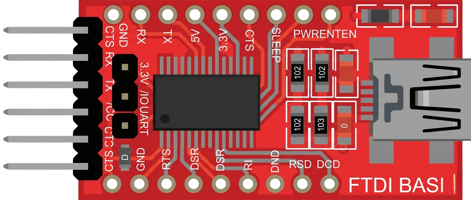
Pin Configuration and Descriptions
The FT232R chip has the following pinout:
| Pin Number | Pin Name | Description |
|---|---|---|
| 1 | TXD | Transmit Data (UART output) |
| 2 | RXD | Receive Data (UART input) |
| 3 | RTS# | Request to Send (active low) |
| 4 | CTS# | Clear to Send (active low) |
| 5 | DTR# | Data Terminal Ready (active low) |
| 6 | DSR# | Data Set Ready (active low) |
| 7 | DCD# | Data Carrier Detect (active low) |
| 8 | RI# | Ring Indicator (active low) |
| 9 | VCC | Power Supply Input (3.3V or 5V) |
| 10 | GND | Ground |
| 11 | USB D+ | USB Data Positive |
| 12 | USB D- | USB Data Negative |
| 13 | RESET# | Reset Input (active low) |
| 14 | 3V3OUT | 3.3V Output (for external use, max 50 mA) |
| 15 | CBUS0 | Configurable I/O Pin |
| 16 | CBUS1 | Configurable I/O Pin |
| 17 | CBUS2 | Configurable I/O Pin |
| 18 | CBUS3 | Configurable I/O Pin |
| 19 | CBUS4 | Configurable I/O Pin |
| 20 | TEST | Test Pin (leave unconnected) |
Usage Instructions
How to Use the FTDI Chip in a Circuit
- Power Supply: Connect the VCC pin to a 3.3V or 5V power source, depending on your system requirements. Ensure the GND pin is connected to the ground of your circuit.
- USB Connection: Connect the USB D+ and USB D- pins to a USB port using a USB cable. These pins handle communication with the host computer.
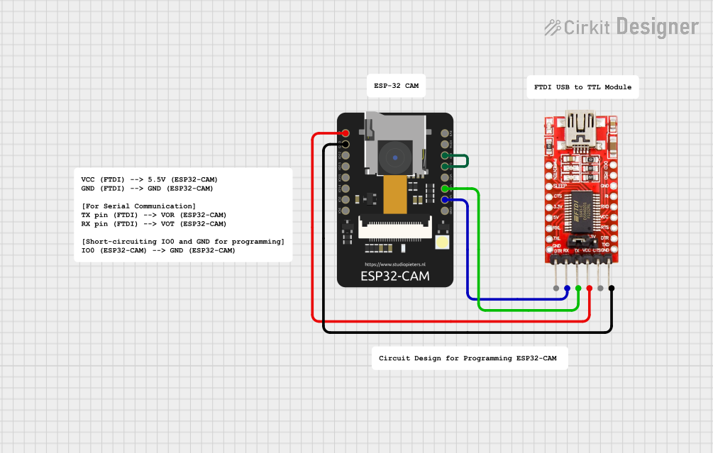
- UART Connection: Connect the TXD and RXD pins to the RX and TX pins of your microcontroller, respectively. Optionally, connect RTS#, CTS#, and other flow control pins if required.
- Driver Installation: Install the appropriate FTDI drivers on your computer. These drivers are available for Windows, macOS, and Linux.
- Configuration: Use the integrated EEPROM to configure the chip's settings, such as baud rate and flow control, using FTDI's software tools.
Important Considerations and Best Practices
- Voltage Levels: Ensure the voltage levels of the FTDI chip match those of the connected microcontroller to avoid damage.
- Driver Compatibility: Always use the latest FTDI drivers to ensure compatibility and performance.
- Decoupling Capacitors: Place decoupling capacitors near the VCC pin to stabilize the power supply.
- Avoid Counterfeit Chips: Purchase FTDI chips from authorized distributors to avoid counterfeit products, which may not work with official drivers.
Example: Connecting FTDI to Arduino UNO
The FTDI chip can be used to program an Arduino UNO or communicate with it via serial. Below is an example Arduino sketch for serial communication:
// Example: Serial communication with FTDI chip
// This sketch sends data from Arduino to the computer via FTDI

void setup() {
  Serial.begin(9600); // Initialize serial communication at 9600 baud
  delay(1000);        // Wait for the FTDI chip to initialize
  Serial.println("FTDI Communication Initialized");
}

void loop() {
  Serial.println("Hello from Arduino!"); // Send data to the computer
  delay(1000);                           // Wait 1 second before sending again
}
Troubleshooting and FAQs
Common Issues and Solutions
FTDI Device Not Recognized by Computer
- Ensure the FTDI drivers are installed correctly.
- Check the USB cable and port for physical damage.
- Verify that the chip is receiving power (check the VCC and GND connections).
No Data Transmission
- Confirm that the TXD and RXD pins are connected correctly.
- Check the baud rate settings in your software and ensure they match the FTDI configuration.
- Verify that the microcontroller is powered and functioning properly.
Intermittent Communication Failures
- Use decoupling capacitors near the power pins to reduce noise.
- Ensure proper grounding between the FTDI chip and the microcontroller.
FAQs
Q: Can I use the FTDI chip with 1.8V logic devices?
A: No, the FTDI FT232R supports 3.3V and 5V logic levels. For 1.8V devices, use a level shifter.
Q: How do I check if my FTDI chip is genuine?
A: Use FTDI's official software tools to verify the chip's authenticity. Counterfeit chips may not work with official drivers.
Q: Can I use the FTDI chip for SPI or I2C communication?
A: The FTDI FT232R is designed for UART communication. For SPI or I2C, consider other FTDI chips like the FT2232H.
Q: What is the maximum cable length for USB communication?
A: The USB 2.0 standard specifies a maximum cable length of 5 meters for reliable communication.