Cirkit Designer Logo
Cirkit Designer
Your all-in-one circuit design IDE
Home / 
Component Documentation

How to Use STM32F103RB: Examples, Pinouts, and Specs

Image of STM32F103RB
Cirkit Designer LogoDesign with STM32F103RB in Cirkit Designer

Introduction

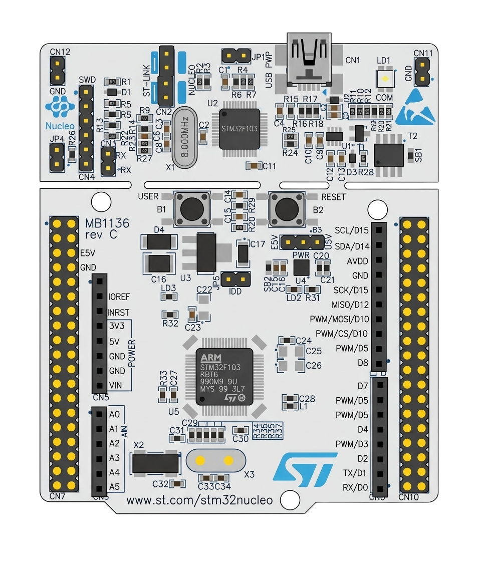
The STM32F103RB is a 32-bit microcontroller developed by STMicroelectronics. It is part of the STM32 family and is based on the ARM Cortex-M3 core. This microcontroller is designed for high-performance applications, offering a clock speed of up to 72 MHz, 128 KB of flash memory, and a wide range of peripherals for communication, control, and data processing.

Explore Projects Built with STM32F103RB

Use Cirkit Designer to design, explore, and prototype these projects online. Some projects support real-time simulation. Click "Open Project" to start designing instantly!
STM32F103C8T6 Battery-Powered LED Indicator Circuit
Image of Assigment.2: A project utilizing STM32F103RB in a practical application
This circuit features an STM32F103C8T6 microcontroller powered by a 3.3V battery, which controls a red LED. The LED is connected to pin A1 of the microcontroller through a 10-ohm resistor to limit the current.
Cirkit Designer LogoOpen Project in Cirkit Designer
Solar-Powered STM32-Based Automation System with Matrix Keypad and RTC
Image of soloar cleaner : A project utilizing STM32F103RB in a practical application
This circuit features an STM32F103C8T6 microcontroller interfaced with a membrane matrix keypad for input, an RTC DS3231 for real-time clock functionality, and a 16x2 I2C LCD for display. It controls four 12V geared motors through two MD20 CYTRON motor drivers, with the motor power supplied by a 12V battery regulated by a buck converter. The battery is charged via a solar panel connected through a solar charge controller, ensuring a renewable energy source for the system.
Cirkit Designer LogoOpen Project in Cirkit Designer
STM32F103C8T6 Bluetooth-Controlled Arcade Joystick Interface
Image of RC카 조이스틱: A project utilizing STM32F103RB in a practical application
This circuit features an STM32F103C8T6 microcontroller interfaced with a Bluetooth HC-06 module for wireless communication and an Adafruit Arcade Joystick for user input. The microcontroller's pins B0 and B10 are connected to the TXD and RXD pins of the Bluetooth module, enabling serial communication, while pins B14 and B15 interface with the joystick's directional controls. The circuit is powered by a battery, with power distribution managed through the microcontroller's 3.3V pin and common ground connections.
Cirkit Designer LogoOpen Project in Cirkit Designer
STM32F103C8T6-Based Water Level Monitoring and Communication System with SIM900A and LoRa Connectivity
Image of water level: A project utilizing STM32F103RB in a practical application
This circuit features a microcontroller (STM32F103C8T6) interfaced with a SIM900A GSM module, an HC-SR04 ultrasonic sensor, a water level sensor, and a LoRa Ra-02 SX1278 module for long-range communication. The STM32F103C8T6 is configured to communicate with the GSM module and LoRa module via serial connections, and it reads data from the ultrasonic and water level sensors. An FTDI Programmer is connected for programming and serial communication with the microcontroller.
Cirkit Designer LogoOpen Project in Cirkit Designer

Explore Projects Built with STM32F103RB

Use Cirkit Designer to design, explore, and prototype these projects online. Some projects support real-time simulation. Click "Open Project" to start designing instantly!
Image of Assigment.2: A project utilizing STM32F103RB in a practical application
STM32F103C8T6 Battery-Powered LED Indicator Circuit
This circuit features an STM32F103C8T6 microcontroller powered by a 3.3V battery, which controls a red LED. The LED is connected to pin A1 of the microcontroller through a 10-ohm resistor to limit the current.
Cirkit Designer LogoOpen Project in Cirkit Designer
Image of soloar cleaner : A project utilizing STM32F103RB in a practical application
Solar-Powered STM32-Based Automation System with Matrix Keypad and RTC
This circuit features an STM32F103C8T6 microcontroller interfaced with a membrane matrix keypad for input, an RTC DS3231 for real-time clock functionality, and a 16x2 I2C LCD for display. It controls four 12V geared motors through two MD20 CYTRON motor drivers, with the motor power supplied by a 12V battery regulated by a buck converter. The battery is charged via a solar panel connected through a solar charge controller, ensuring a renewable energy source for the system.
Cirkit Designer LogoOpen Project in Cirkit Designer
Image of RC카 조이스틱: A project utilizing STM32F103RB in a practical application
STM32F103C8T6 Bluetooth-Controlled Arcade Joystick Interface
This circuit features an STM32F103C8T6 microcontroller interfaced with a Bluetooth HC-06 module for wireless communication and an Adafruit Arcade Joystick for user input. The microcontroller's pins B0 and B10 are connected to the TXD and RXD pins of the Bluetooth module, enabling serial communication, while pins B14 and B15 interface with the joystick's directional controls. The circuit is powered by a battery, with power distribution managed through the microcontroller's 3.3V pin and common ground connections.
Cirkit Designer LogoOpen Project in Cirkit Designer
Image of water level: A project utilizing STM32F103RB in a practical application
STM32F103C8T6-Based Water Level Monitoring and Communication System with SIM900A and LoRa Connectivity
This circuit features a microcontroller (STM32F103C8T6) interfaced with a SIM900A GSM module, an HC-SR04 ultrasonic sensor, a water level sensor, and a LoRa Ra-02 SX1278 module for long-range communication. The STM32F103C8T6 is configured to communicate with the GSM module and LoRa module via serial connections, and it reads data from the ultrasonic and water level sensors. An FTDI Programmer is connected for programming and serial communication with the microcontroller.
Cirkit Designer LogoOpen Project in Cirkit Designer

Common Applications and Use Cases

  • Industrial automation and control systems
  • Consumer electronics
  • IoT devices and smart home applications
  • Motor control and robotics
  • Medical devices
  • Data acquisition systems

Technical Specifications

Key Technical Details

Parameter Value
Core ARM Cortex-M3
Clock Speed Up to 72 MHz
Flash Memory 128 KB
SRAM 20 KB
Operating Voltage 2.0 V to 3.6 V
GPIO Pins 51
Communication Interfaces USART, SPI, I2C, CAN, USB
Timers 3 general-purpose, 1 advanced
ADC 12-bit, up to 16 channels
Package LQFP64 (64-pin)

Pin Configuration and Descriptions

The STM32F103RB comes in an LQFP64 package with 64 pins. Below is a table summarizing the key pin functions:

Pin Number Pin Name Function(s)
1 VDD Power supply (3.3 V)
2 VSS Ground
10 PA0 GPIO, ADC_IN0, WKUP
22 PB6 GPIO, I2C1_SCL, USART1_TX
23 PB7 GPIO, I2C1_SDA, USART1_RX
31 PC13 GPIO, TAMPER-RTC
50 PA9 GPIO, USART1_TX
51 PA10 GPIO, USART1_RX
64 NRST Reset

For a complete pinout, refer to the STM32F103RB datasheet provided by STMicroelectronics.

Usage Instructions

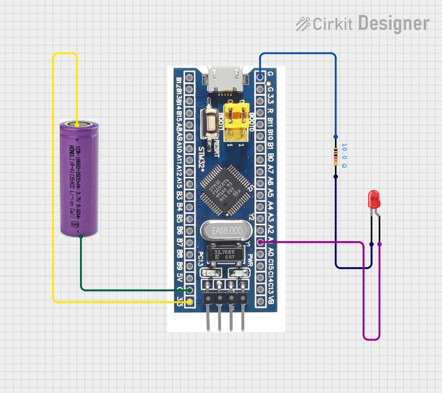
How to Use the STM32F103RB in a Circuit

  1. Power Supply: Connect the VDD pin to a 3.3 V power source and the VSS pin to ground.
  2. Clock Configuration: Use an external 8 MHz crystal oscillator for precise clocking or configure the internal RC oscillator.
  3. Programming: Use an ST-Link programmer/debugger to upload firmware via the SWD (Serial Wire Debug) interface.
  4. Peripherals: Connect peripherals (e.g., sensors, actuators) to the GPIO pins. Configure the pins in the firmware for the desired functionality (e.g., input, output, alternate function).
  5. Communication: Utilize USART, SPI, I2C, or CAN interfaces for communication with other devices.

Important Considerations and Best Practices

  • Voltage Levels: Ensure all connected devices operate within the 3.3 V logic level to avoid damage.
  • Decoupling Capacitors: Place 0.1 µF decoupling capacitors close to the VDD pins to stabilize the power supply.
  • Boot Modes: Configure the BOOT0 and BOOT1 pins to select the desired boot mode (e.g., boot from flash memory).
  • Debugging: Use the SWD interface for debugging and firmware updates.
  • Code Optimization: Leverage the ARM Cortex-M3's advanced features, such as interrupt handling and low-power modes, for efficient operation.

Example Code for Arduino IDE (Using STM32 Core)

The STM32F103RB can be programmed using the Arduino IDE with the STM32 core installed. Below is an example of blinking an LED connected to pin PA5:

// Define the LED pin
#define LED_PIN PA5

void setup() {
  // Set the LED pin as output
  pinMode(LED_PIN, OUTPUT);
}

void loop() {
  // Turn the LED on
  digitalWrite(LED_PIN, HIGH);
  delay(500); // Wait for 500 ms
  
  // Turn the LED off
  digitalWrite(LED_PIN, LOW);
  delay(500); // Wait for 500 ms
}

Note: Install the STM32 core in the Arduino IDE by navigating to File > Preferences, adding the STM32 board manager URL, and installing the STM32 package via the Board Manager.

Troubleshooting and FAQs

Common Issues and Solutions

  1. Microcontroller Not Responding

    • Cause: Incorrect power supply or boot mode configuration.
    • Solution: Verify the power supply voltage (3.3 V) and ensure BOOT0 is set to boot from flash memory.
  2. Programming Failure

    • Cause: Faulty connection to the ST-Link programmer.
    • Solution: Check the SWD connections (SWCLK, SWDIO, GND, and VDD) and ensure the ST-Link driver is installed.
  3. Peripheral Not Working

    • Cause: Incorrect pin configuration in the firmware.
    • Solution: Double-check the pin assignments and ensure the peripheral clock is enabled in the firmware.
  4. Overheating

    • Cause: Excessive current draw or short circuit.
    • Solution: Inspect the circuit for shorts and ensure the microcontroller is not overloaded.

FAQs

  • Q: Can the STM32F103RB operate at 5 V?
    A: No, the STM32F103RB operates at a voltage range of 2.0 V to 3.6 V. Use level shifters for 5 V devices.

  • Q: How do I reset the microcontroller?
    A: Use the NRST pin or issue a software reset command in the firmware.

  • Q: Can I use the STM32F103RB for USB communication?
    A: Yes, the STM32F103RB has a USB 2.0 full-speed interface for communication.

  • Q: What development tools are recommended?
    A: Use STM32CubeIDE, Keil uVision, or the Arduino IDE with the STM32 core for development.

This concludes the documentation for the STM32F103RB microcontroller. For further details, refer to the official datasheet and reference manual provided by STMicroelectronics.