How to Use GMT020 display1: Examples, Pinouts, and Specs
Introduction
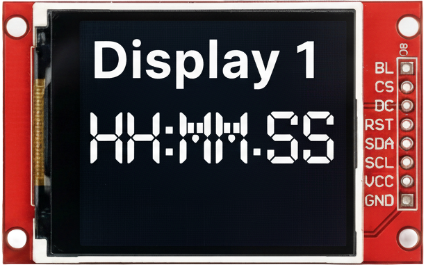
The GMT020 Display1 is a compact LCD display module designed for displaying alphanumeric characters and simple graphics. Its small size and versatility make it an excellent choice for embedded systems, DIY electronics projects, and industrial applications. The module is easy to interface with microcontrollers, such as Arduino, Raspberry Pi, and other development boards, making it a popular choice for hobbyists and professionals alike.
Explore Projects Built with GMT020 display1


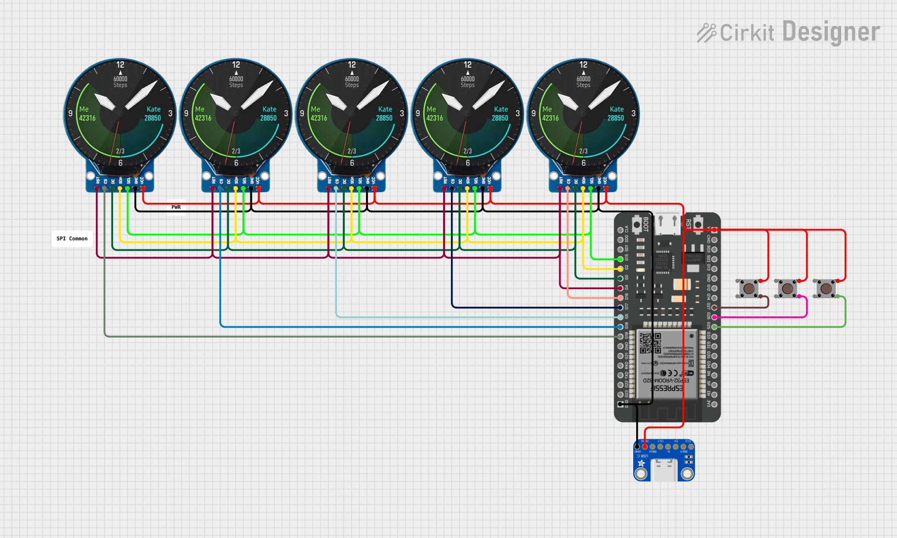
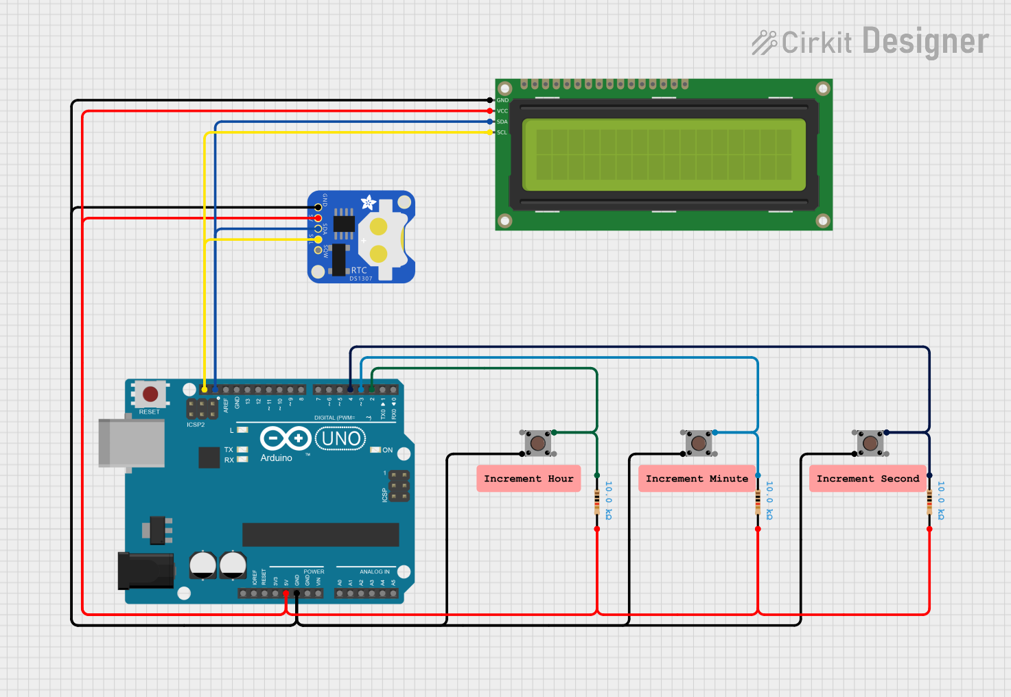
Explore Projects Built with GMT020 display1
Common Applications and Use Cases
- Displaying sensor data in IoT projects
- User interfaces for embedded systems
- Digital clocks and timers
- Menu systems for electronic devices
- Educational and prototyping projects
Technical Specifications
The GMT020 Display1 is designed to operate efficiently in a variety of environments. Below are its key technical details:
General Specifications
| Parameter | Value |
|---|---|
| Display Type | LCD (Alphanumeric/Graphics) |
| Resolution | 16x2 (16 characters, 2 lines) |
| Operating Voltage | 3.3V - 5V DC |
| Operating Current | 2mA (typical) |
| Backlight | LED (White) |
| Communication Interface | Parallel (4-bit or 8-bit) |
| Dimensions | 80mm x 36mm x 12mm |
| Operating Temperature | -20°C to 70°C |
Pin Configuration and Descriptions
The GMT020 Display1 has a 16-pin interface for connecting to a microcontroller or other control circuits. Below is the pinout and description:
| Pin Number | Name | Description |
|---|---|---|
| 1 | VSS | Ground (0V) connection |
| 2 | VDD | Power supply (3.3V or 5V) |
| 3 | VO | Contrast adjustment (connect to a potentiometer for contrast control) |
| 4 | RS | Register Select (0: Command mode, 1: Data mode) |
| 5 | RW | Read/Write control (0: Write, 1: Read) |
| 6 | E | Enable signal (used to latch data) |
| 7-14 | D0-D7 | Data bus lines (D0-D3 optional in 4-bit mode) |
| 15 | LED+ | Backlight anode (connect to 5V via a resistor) |
| 16 | LED- | Backlight cathode (connect to ground) |
Usage Instructions
The GMT020 Display1 can be used in either 4-bit or 8-bit communication mode. Below are the steps to integrate the display into your project:
Connecting the Display
- Power Supply: Connect
VSSto ground andVDDto a 3.3V or 5V power source. - Contrast Adjustment: Connect
VOto the wiper of a 10kΩ potentiometer. Connect one end of the potentiometer to ground and the other to 5V. - Control Pins: Connect
RS,RW, andEto digital pins on your microcontroller. - Data Pins: For 4-bit mode, connect only
D4-D7to the microcontroller. For 8-bit mode, connect allD0-D7. - Backlight: Connect
LED+to 5V through a 220Ω resistor andLED-to ground.
Arduino UNO Example Code
Below is an example of how to use the GMT020 Display1 with an Arduino UNO in 4-bit mode:
#include <LiquidCrystal.h>

// Initialize the library with the pins connected to the display
// RS, E, D4, D5, D6, D7
LiquidCrystal lcd(7, 8, 9, 10, 11, 12);

void setup() {
  // Set up the LCD's number of columns and rows
  lcd.begin(16, 2);

  // Print a message to the LCD
  lcd.print("Hello, World!");
}

void loop() {
  // Move the cursor to the second line, first column
  lcd.setCursor(0, 1);

  // Print the current time in seconds since the Arduino started
  lcd.print(millis() / 1000);
}
Important Considerations
- Contrast Adjustment: Ensure the contrast is properly set using the potentiometer. If the display is blank, adjust the potentiometer until characters are visible.
- Backlight Resistor: Always use a resistor (e.g., 220Ω) in series with the backlight to prevent damage.
- Initialization: Ensure the display is initialized correctly in your code. Use libraries like
LiquidCrystalfor Arduino to simplify this process.
Troubleshooting and FAQs
Common Issues
Display Not Turning On
- Check the power connections (
VSSandVDD). - Verify the backlight connections (
LED+andLED-).
- Check the power connections (
No Characters Displayed
- Adjust the contrast using the potentiometer connected to
VO. - Ensure the
RS,RW, andEpins are correctly connected and configured in the code.
- Adjust the contrast using the potentiometer connected to
Garbled or Incorrect Characters
- Verify the data pin connections (
D4-D7orD0-D7). - Ensure the correct communication mode (4-bit or 8-bit) is selected in the code.
- Verify the data pin connections (
Backlight Not Working
- Check the resistor value in series with
LED+. - Ensure
LED+is connected to 5V andLED-to ground.
- Check the resistor value in series with
FAQs
Q: Can I use the GMT020 Display1 with a 3.3V microcontroller?
A: Yes, the display is compatible with both 3.3V and 5V systems. Ensure the backlight resistor is appropriately sized for 3.3V operation.
Q: How do I display custom characters?
A: Use the createChar() function in the LiquidCrystal library to define and display custom characters.
Q: Can I use the display without a backlight?
A: Yes, the display will still function without the backlight, but visibility may be reduced in low-light conditions.
Q: What is the maximum cable length for connecting the display?
A: Keep the cable length as short as possible (preferably under 30cm) to avoid signal degradation, especially in 4-bit mode.
By following this documentation, you can effectively integrate and troubleshoot the GMT020 Display1 in your projects.