How to Use Converter DC DC: Examples, Pinouts, and Specs
Introduction
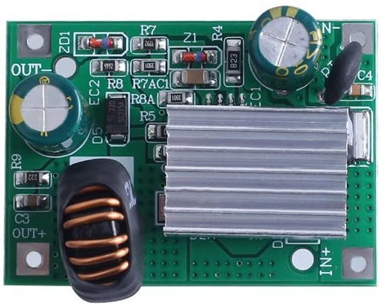
A DC-DC converter is an electronic device designed to convert direct current (DC) from one voltage level to another. This component is essential for efficient power management in electronic circuits, enabling devices to operate at their required voltage levels regardless of the input power source. Manufactured by Китай, this DC-DC converter is versatile and widely used in various applications.
Explore Projects Built with Converter DC DC


Explore Projects Built with Converter DC DC
Common Applications and Use Cases
- Powering microcontrollers and sensors in embedded systems
- Voltage regulation in battery-powered devices
- Step-up (boost) or step-down (buck) voltage conversion for portable electronics
- Renewable energy systems, such as solar panels
- Automotive electronics for voltage stabilization
Technical Specifications
Below are the key technical details of the DC-DC converter:
| Parameter | Value |
|---|---|
| Input Voltage Range | 3V to 40V |
| Output Voltage Range | 1.25V to 37V |
| Maximum Output Current | 2A (with proper heat dissipation) |
| Efficiency | Up to 92% |
| Switching Frequency | 150 kHz |
| Operating Temperature | -40°C to +85°C |
| Dimensions | 43mm x 21mm x 14mm |
Pin Configuration and Descriptions
The DC-DC converter typically has the following pin configuration:
| Pin Name | Description |
|---|---|
| VIN | Input voltage pin. Connect the DC power source here. |
| GND | Ground pin. Connect to the circuit ground. |
| VOUT | Output voltage pin. Provides the regulated voltage. |
| ADJ | Adjustment pin. Used to set the output voltage. |
Usage Instructions
How to Use the Component in a Circuit
Connect the Input Voltage (VIN):
Attach the positive terminal of your DC power source to the VIN pin and the negative terminal to the GND pin.Set the Output Voltage (VOUT):
Use a multimeter to measure the output voltage at the VOUT pin. Adjust the potentiometer (if available) or the ADJ pin to set the desired output voltage.Connect the Load:
Attach the load (e.g., microcontroller, sensor, or other devices) to the VOUT pin and GND pin.Verify Connections:
Double-check all connections to ensure proper polarity and secure wiring.
Important Considerations and Best Practices
- Heat Dissipation: Ensure adequate heat dissipation, especially when operating at high currents. Use a heatsink if necessary.
- Input Voltage Range: Do not exceed the specified input voltage range (3V to 40V) to avoid damaging the component.
- Output Voltage Adjustment: When adjusting the output voltage, turn the potentiometer slowly to prevent overshooting the desired voltage.
- Capacitors: Add input and output capacitors (e.g., 10µF to 100µF) close to the converter to reduce voltage ripple and improve stability.
- Polarity Protection: Use a diode at the input to protect against reverse polarity connections.
Example: Using the DC-DC Converter with an Arduino UNO
Below is an example of how to use the DC-DC converter to power an Arduino UNO with a 12V input source:
Circuit Connections
- Connect the 12V power source to the VIN and GND pins of the DC-DC converter.
- Adjust the output voltage to 5V using the potentiometer or ADJ pin.
- Connect the VOUT pin to the 5V pin of the Arduino UNO.
- Connect the GND pin of the converter to the GND pin of the Arduino UNO.
Sample Code
// Example code to blink an LED using Arduino UNO powered by a DC-DC converter

const int ledPin = 13; // Pin connected to the onboard LED

void setup() {
  pinMode(ledPin, OUTPUT); // Set the LED pin as an output
}

void loop() {
  digitalWrite(ledPin, HIGH); // Turn the LED on
  delay(1000);                // Wait for 1 second
  digitalWrite(ledPin, LOW);  // Turn the LED off
  delay(1000);                // Wait for 1 second
}
Troubleshooting and FAQs
Common Issues and Solutions
No Output Voltage:
- Cause: Incorrect wiring or loose connections.
Solution: Verify all connections and ensure proper polarity. - Cause: Input voltage is outside the specified range.
Solution: Check the input voltage and ensure it is within 3V to 40V.
- Cause: Incorrect wiring or loose connections.
Output Voltage is Unstable:
- Cause: Insufficient input or output capacitors.
Solution: Add capacitors (e.g., 10µF to 100µF) close to the VIN and VOUT pins. - Cause: Load exceeds the maximum current rating.
Solution: Reduce the load or use a higher-rated DC-DC converter.
- Cause: Insufficient input or output capacitors.
Overheating:
- Cause: High current draw without proper heat dissipation.
Solution: Attach a heatsink or improve ventilation around the converter.
- Cause: High current draw without proper heat dissipation.
Output Voltage Does Not Match the Set Value:
- Cause: Potentiometer not adjusted correctly.
Solution: Re-adjust the potentiometer while monitoring the output voltage with a multimeter.
- Cause: Potentiometer not adjusted correctly.
FAQs
Q: Can this DC-DC converter be used for both step-up and step-down applications?
A: No, this specific model is a step-down (buck) converter. It can only reduce the input voltage to a lower output voltage.
Q: What is the maximum power output of this converter?
A: The maximum power output depends on the input voltage and current. For example, at 12V input and 2A output, the power is 24W.
Q: Can I use this converter with a lithium-ion battery?
A: Yes, as long as the battery voltage is within the input voltage range (3V to 40V).
Q: Is reverse polarity protection included?
A: No, reverse polarity protection is not built-in. You should add a diode at the input to prevent damage.
By following this documentation, you can effectively integrate the DC-DC converter into your projects and troubleshoot common issues.