How to Use 4-Channel Optocoupler Photoelectric Isolator Module: Examples, Pinouts, and Specs
Introduction
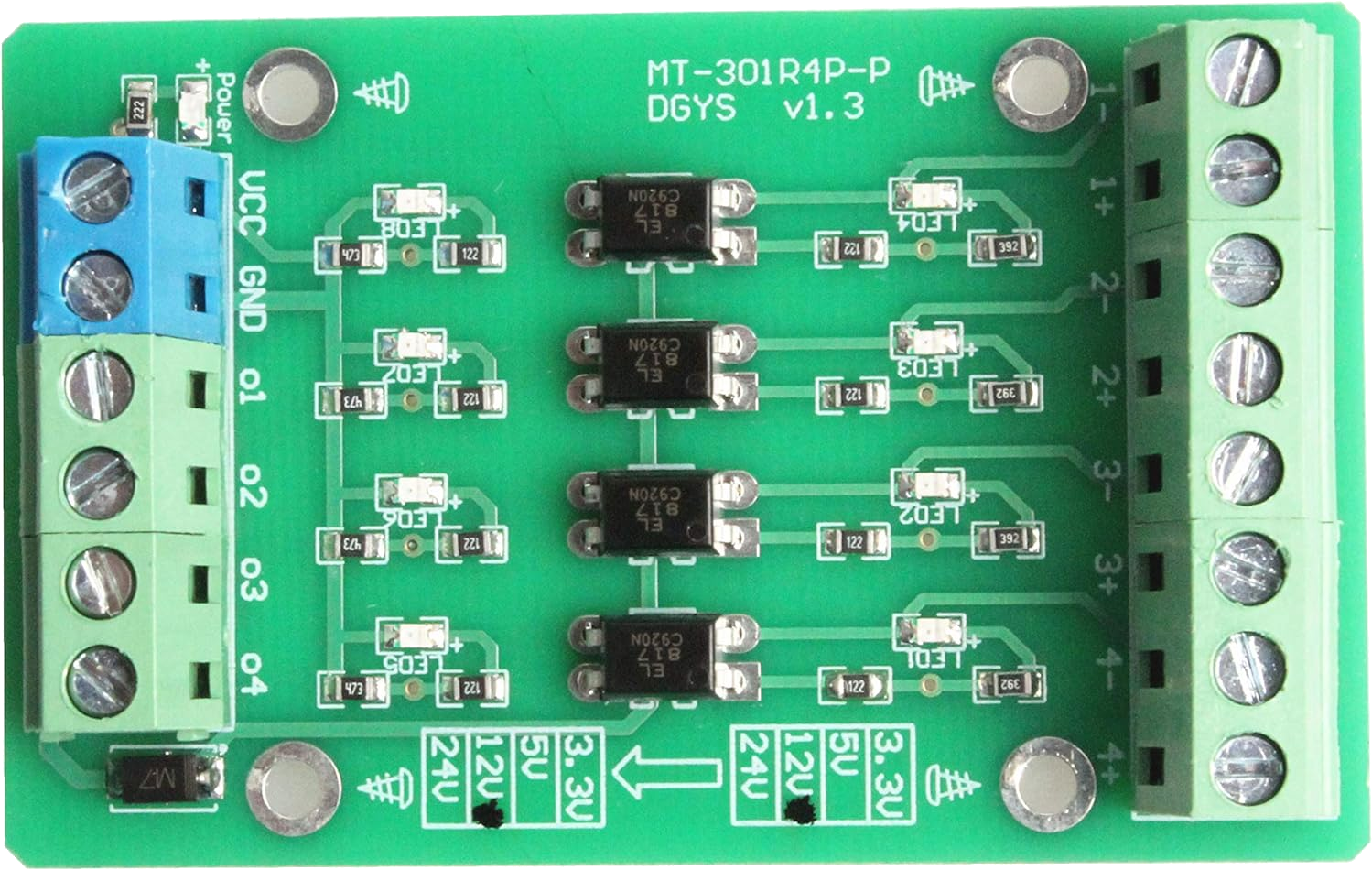
The 4-Channel Optocoupler Photoelectric Isolator Module by NOYITO (Part ID: PNP NPN to NPN, 12V to 3.3V) is a versatile electronic component designed to provide electrical isolation between different parts of a circuit. It uses optocouplers to transmit signals while preventing direct electrical connections, ensuring safety and protecting sensitive components from voltage spikes, noise, or ground loops.
This module is particularly useful in applications where signal integrity and isolation are critical, such as:
- Microcontroller interfacing with high-voltage systems
- Industrial automation and control systems
- Signal level shifting (e.g., 12V to 3.3V)
- Noise suppression in communication lines
Explore Projects Built with 4-Channel Optocoupler Photoelectric Isolator Module


Explore Projects Built with 4-Channel Optocoupler Photoelectric Isolator Module
Technical Specifications
The following table outlines the key technical details of the module:
| Parameter | Specification |
|---|---|
| Operating Voltage (Input) | 12V |
| Output Voltage | 3.3V |
| Channels | 4 |
| Isolation Voltage | ≥ 2500V |
| Input Signal Type | PNP/NPN |
| Output Signal Type | NPN |
| Response Time | ≤ 4 µs |
| Dimensions | 50mm x 40mm x 15mm |
Pin Configuration and Descriptions
The module has a total of 10 pins, distributed as follows:
Input Side (High Voltage, 12V Logic)
| Pin | Label | Description |
|---|---|---|
| 1 | IN1 | Input signal for Channel 1 (PNP/NPN) |
| 2 | IN2 | Input signal for Channel 2 (PNP/NPN) |
| 3 | IN3 | Input signal for Channel 3 (PNP/NPN) |
| 4 | IN4 | Input signal for Channel 4 (PNP/NPN) |
| 5 | GND | Ground (common for input side) |
Output Side (Low Voltage, 3.3V Logic)
| Pin | Label | Description |
|---|---|---|
| 6 | OUT1 | Output signal for Channel 1 (NPN) |
| 7 | OUT2 | Output signal for Channel 2 (NPN) |
| 8 | OUT3 | Output signal for Channel 3 (NPN) |
| 9 | OUT4 | Output signal for Channel 4 (NPN) |
| 10 | GND | Ground (common for output side) |
Usage Instructions
How to Use the Module in a Circuit
- Power the Module: Connect the input side to a 12V power source and the output side to a 3.3V system. Ensure the grounds of both sides are properly connected.
- Connect Input Signals: Feed the high-voltage signals (PNP or NPN) to the
IN1toIN4pins. These signals will be optically isolated and converted to low-voltage NPN signals. - Connect Output Signals: Use the
OUT1toOUT4pins to interface with the 3.3V logic system, such as a microcontroller or other low-voltage devices. - Verify Connections: Double-check all connections to ensure proper operation and avoid damage to the module or connected devices.
Important Considerations and Best Practices
- Isolation: Ensure that the input and output grounds are not directly connected to maintain proper isolation.
- Signal Polarity: Verify the input signal type (PNP or NPN) and ensure compatibility with the module.
- Load Requirements: The output signals are NPN open-collector types, so pull-up resistors may be required for proper operation.
- Voltage Levels: Do not exceed the specified input and output voltage ratings to avoid damage to the module.
Example: Connecting to an Arduino UNO
The following example demonstrates how to use the module to interface a 12V signal with an Arduino UNO:
Circuit Connections
- Connect
IN1to a 12V signal source. - Connect
OUT1to Arduino digital pin 2. - Connect the input
GNDto the 12V system ground. - Connect the output
GNDto the Arduino ground.
Arduino Code
// Example code for reading a signal from the 4-Channel Optocoupler Module
// Connect OUT1 of the module to Arduino digital pin 2

const int optoInputPin = 2; // Define the pin connected to OUT1
int signalState = 0;        // Variable to store the signal state

void setup() {
  pinMode(optoInputPin, INPUT); // Set the pin as input
  Serial.begin(9600);          // Initialize serial communication
}

void loop() {
  signalState = digitalRead(optoInputPin); // Read the signal state

  // Print the signal state to the Serial Monitor
  if (signalState == HIGH) {
    Serial.println("Signal HIGH detected");
  } else {
    Serial.println("Signal LOW detected");
  }

  delay(500); // Wait for 500ms before the next reading
}
Troubleshooting and FAQs
Common Issues and Solutions
No Output Signal Detected
- Cause: Incorrect input signal type or insufficient input voltage.
- Solution: Verify the input signal type (PNP/NPN) and ensure it meets the 12V requirement.
Output Signal Not Recognized by Microcontroller
- Cause: Missing pull-up resistor on the output pin.
- Solution: Add a pull-up resistor (e.g., 10kΩ) between the output pin and the 3.3V supply.
Module Overheating
- Cause: Exceeding the voltage or current ratings.
- Solution: Ensure the input and output voltages are within the specified range.
Ground Loop Issues
- Cause: Input and output grounds are directly connected.
- Solution: Maintain isolation by keeping the input and output grounds separate.
FAQs
Q1: Can this module be used with 5V logic systems?
A1: Yes, the output side can interface with 5V systems, but ensure the pull-up resistor is connected to the 5V supply.
Q2: What is the maximum frequency this module can handle?
A2: The module has a response time of ≤ 4 µs, allowing it to handle signals up to approximately 250 kHz.
Q3: Can I use fewer than 4 channels?
A3: Yes, unused channels can be left unconnected without affecting the operation of the other channels.
Q4: Is this module suitable for AC signals?
A4: No, this module is designed for DC signals only. For AC signals, consider using an AC-compatible optocoupler module.