How to Use 24/12v Buck: Examples, Pinouts, and Specs
Introduction
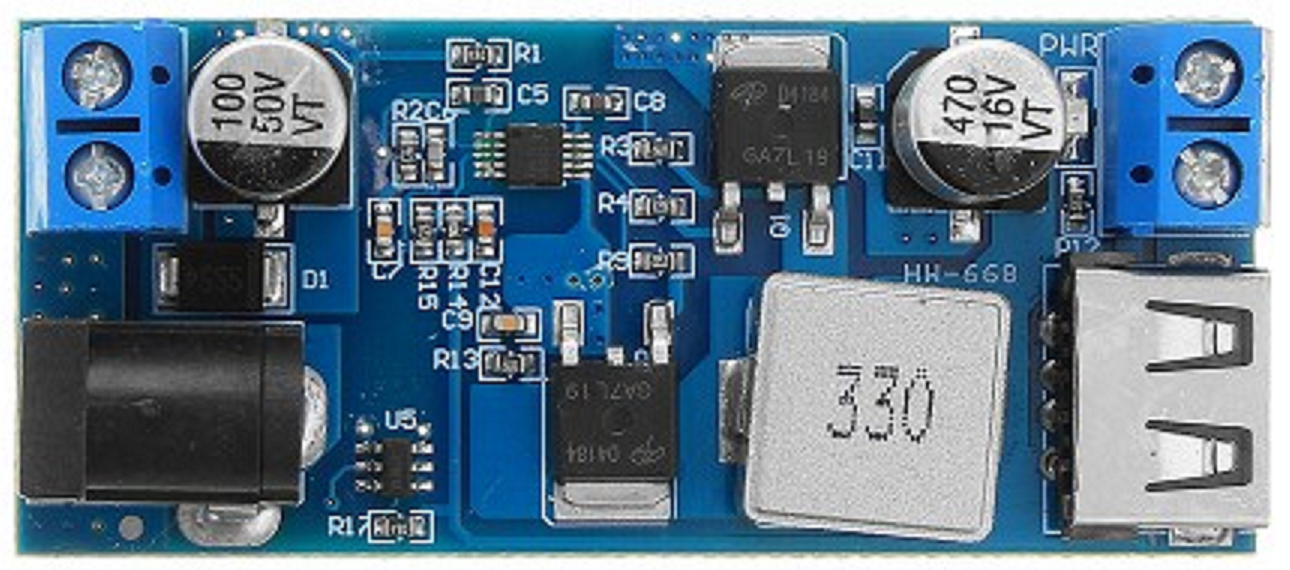
The 24/12V Buck Converter (Manufacturer: Arduino, Part ID: UNO) is a DC-DC step-down voltage regulator designed to efficiently convert a 24V input to a stable 12V output. This component is ideal for applications requiring a lower voltage supply from a higher voltage source, such as powering 12V devices from a 24V battery or industrial power systems. Its high efficiency minimizes power loss, making it suitable for energy-sensitive applications.
Explore Projects Built with 24/12v Buck


Explore Projects Built with 24/12v Buck
Common Applications and Use Cases
- Powering 12V devices (e.g., fans, LEDs, sensors) from a 24V power source
- Industrial automation systems
- Automotive electronics
- Renewable energy systems (e.g., solar panels)
- Battery-powered devices requiring voltage regulation
Technical Specifications
The following table outlines the key technical details of the 24/12V Buck Converter:
| Parameter | Value |
|---|---|
| Input Voltage Range | 18V to 26V |
| Output Voltage | 12V ± 0.5V |
| Maximum Output Current | 5A |
| Efficiency | Up to 95% |
| Switching Frequency | 150 kHz |
| Operating Temperature | -40°C to +85°C |
| Dimensions | 45mm x 25mm x 15mm |
Pin Configuration and Descriptions
The 24/12V Buck Converter has the following pin configuration:
| Pin Name | Description |
|---|---|
| VIN | Input voltage pin (connect to 24V power source) |
| GND | Ground pin (common ground for input and output) |
| VOUT | Output voltage pin (provides regulated 12V output) |
| EN | Enable pin (active high; connect to logic HIGH to enable) |
Usage Instructions
How to Use the Component in a Circuit
Connect the Input Voltage (VIN):
Attach the VIN pin to a 24V DC power source. Ensure the input voltage is within the specified range (18V to 26V) to avoid damage to the converter.Connect the Ground (GND):
Connect the GND pin to the common ground of your circuit.Connect the Output Voltage (VOUT):
Attach the VOUT pin to the load requiring 12V. Ensure the load does not exceed the maximum output current of 5A.Enable the Converter (Optional):
If the EN pin is available, connect it to a logic HIGH signal (e.g., 5V from an Arduino) to enable the converter. Leave it unconnected or pull it LOW to disable the output.
Important Considerations and Best Practices
- Heat Dissipation: The converter may generate heat under high loads. Use a heatsink or ensure proper ventilation to maintain safe operating temperatures.
- Input Voltage Range: Always ensure the input voltage is within the specified range (18V to 26V). Exceeding this range can damage the component.
- Output Filtering: For sensitive applications, consider adding a capacitor (e.g., 100µF) at the output to reduce noise and ripple.
- Load Current: Do not exceed the maximum output current of 5A to prevent overheating or damage.
Example: Connecting to an Arduino UNO
The 24/12V Buck Converter can be used to power an Arduino UNO from a 24V power source. Below is an example circuit and code to enable the converter using the EN pin.
Circuit Diagram
- Connect the VIN pin of the buck converter to the 24V power source.
- Connect the GND pin to the common ground of the circuit.
- Connect the VOUT pin to the Arduino UNO's VIN pin (to supply 12V to the Arduino).
- Connect the EN pin to a digital output pin on the Arduino (e.g., pin 7).
Example Code
// Example code to enable the 24/12V Buck Converter using the EN pin
// Connect the EN pin of the buck converter to Arduino pin 7

const int enablePin = 7; // Pin connected to the EN pin of the buck converter

void setup() {
  pinMode(enablePin, OUTPUT); // Set pin 7 as an output
  digitalWrite(enablePin, HIGH); // Enable the buck converter
}

void loop() {
  // The buck converter remains enabled in this example
  // Add your application code here
}
Troubleshooting and FAQs
Common Issues and Solutions
No Output Voltage:
- Cause: The EN pin is not connected or is pulled LOW.
- Solution: Connect the EN pin to a logic HIGH signal (e.g., 5V) to enable the converter.
Overheating:
- Cause: Excessive load current or poor ventilation.
- Solution: Ensure the load current does not exceed 5A. Use a heatsink or improve airflow around the converter.
Output Voltage Fluctuations:
- Cause: Insufficient input voltage or high ripple.
- Solution: Verify the input voltage is stable and within the specified range. Add a capacitor (e.g., 100µF) at the output to reduce ripple.
Noisy Output:
- Cause: High-frequency switching noise.
- Solution: Add a low-pass filter or capacitor at the output to smooth the voltage.
FAQs
Q: Can I use the 24/12V Buck Converter with a 12V input?
A: No, the input voltage must be at least 18V for proper operation. Using a 12V input will result in no output or unstable performance.
Q: Is the converter protected against short circuits?
A: Many buck converters include short-circuit protection, but it is recommended to check the specific datasheet or test the component to confirm.
Q: Can I use the converter to power multiple devices?
A: Yes, as long as the total current draw does not exceed 5A. Use proper wiring to distribute the load evenly.
Q: What happens if the input voltage exceeds 26V?
A: Exceeding the maximum input voltage can damage the converter. Use a voltage regulator or protection circuit to prevent overvoltage.