
How to Use Schneider DM3141: Examples, Pinouts, and Specs
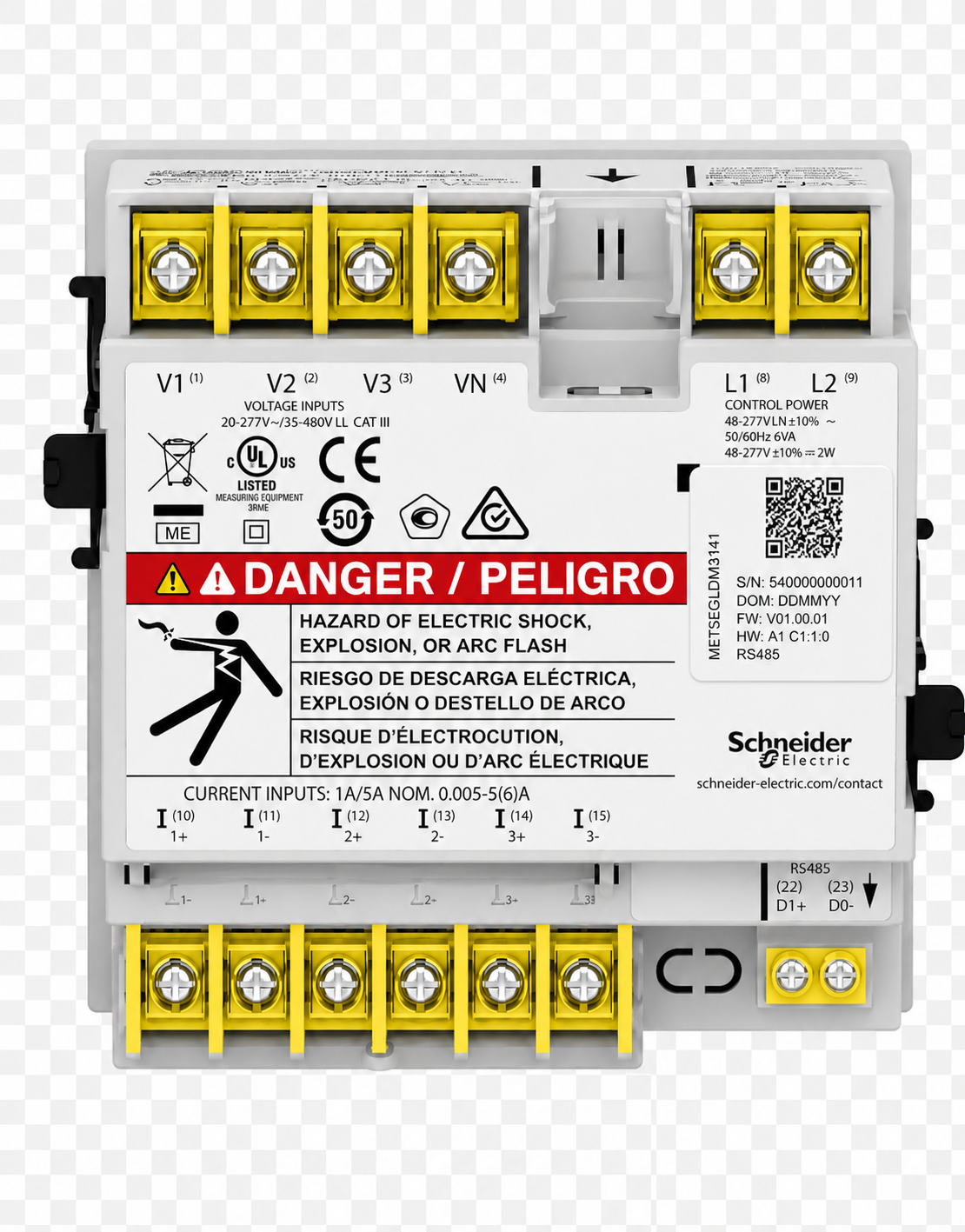
 Design with Schneider DM3141 in Cirkit Designer
Introduction
The Schneider DM3141 is a versatile digital multimeter designed for accurate measurement of voltage, current, and resistance. It is equipped with a clear LCD display, user-friendly controls, and robust construction, making it suitable for both professional electricians and DIY enthusiasts. This multimeter is ideal for troubleshooting electrical circuits, testing components, and performing routine maintenance tasks.
Explore Projects Built with Schneider DM3141
 Open Project in Cirkit Designer
 Open Project in Cirkit Designer
 Open Project in Cirkit Designer
 Open Project in Cirkit Designer
Explore Projects Built with Schneider DM3141
Open Project in Cirkit DesignerOpen Project in Cirkit DesignerOpen Project in Cirkit DesignerOpen Project in Cirkit DesignerCommon Applications and Use Cases
- Measuring AC/DC voltage in electrical circuits
- Testing current flow in devices and systems
- Checking resistance in components such as resistors and wires
- Diagnosing faults in home appliances, automotive systems, and industrial equipment
- Educational purposes for learning basic electronics
Technical Specifications
The Schneider DM3141 is designed to meet the needs of a wide range of users with its reliable performance and essential features.
Key Technical Details
| Parameter | Specification |
|---|---|
| Measurement Functions | Voltage (AC/DC), Current (AC/DC), Resistance |
| Voltage Range | 0 - 600V (AC/DC) |
| Current Range | 0 - 10A (AC/DC) |
| Resistance Range | 0 - 40MΩ |
| Display Type | LCD with backlight |
| Power Supply | 9V battery (standard 6F22) |
| Accuracy | ±0.5% (varies by range) |
| Dimensions | 150mm x 70mm x 35mm |
| Weight | 200g |
| Safety Rating | CAT III 600V |
Pin Configuration and Descriptions
The Schneider DM3141 features three input ports for connecting test probes. Below is the description of each port:
| Port Name | Description |
|---|---|
| COM | Common ground connection for all measurements. Connect the black probe here. |
| VΩmA | Input for measuring voltage, resistance, and current up to 200mA. |
| 10A | Dedicated input for measuring current up to 10A. |
Usage Instructions
The Schneider DM3141 is straightforward to use, but following proper procedures ensures accurate measurements and safety.
How to Use the Component in a Circuit
- Power On the Multimeter: Insert a 9V battery into the battery compartment and turn the rotary switch to the desired measurement mode (e.g., voltage, current, resistance).
- Connect the Probes:
- Insert the black probe into the
COMport. - Insert the red probe into the appropriate port (
VΩmAfor most measurements or10Afor high current).
- Insert the black probe into the
- Select the Measurement Range:
- For manual range selection, turn the rotary switch to the closest higher range of the expected value.
- For auto-ranging models, the multimeter will automatically select the appropriate range.
- Perform the Measurement:
- For voltage: Connect the probes across the component or circuit.
- For current: Break the circuit and connect the probes in series.
- For resistance: Disconnect the component from the circuit and connect the probes across it.
- Read the Display: The measured value will appear on the LCD screen.
Important Considerations and Best Practices
- Always start with the highest range to avoid overloading the multimeter.
- Never measure resistance in a live circuit to prevent damage to the device.
- Use the
10Aport only for high-current measurements and for short durations to avoid overheating. - Replace the battery promptly when the low battery indicator appears to ensure accurate readings.
- Observe the safety rating (CAT III 600V) and avoid using the multimeter in circuits exceeding this limit.
Example: Measuring Voltage with Arduino UNO
The Schneider DM3141 can be used to measure the voltage output of an Arduino UNO. Below is an example:
- Connect the black probe to the
COMport and the red probe to theVΩmAport. - Set the rotary switch to the DC voltage range (e.g., 20V).
- Connect the black probe to the Arduino's GND pin and the red probe to the 5V pin.
- Read the voltage on the multimeter display (should be approximately 5V).
Troubleshooting and FAQs
Common Issues Users Might Face
No Display or Multimeter Not Turning On:
- Cause: Dead or improperly installed battery.
- Solution: Replace the 9V battery and ensure correct polarity.
Inaccurate Readings:
- Cause: Low battery, incorrect range selection, or damaged probes.
- Solution: Replace the battery, select the correct range, and inspect the probes for damage.
Overload Indication ("OL" on Display):
- Cause: Measured value exceeds the selected range.
- Solution: Switch to a higher range or ensure the circuit is within the multimeter's limits.
Burnt Fuse:
- Cause: Measuring high current in the
VΩmAport. - Solution: Replace the internal fuse with the specified type.
- Cause: Measuring high current in the
Solutions and Tips for Troubleshooting
- Always verify the multimeter's settings before connecting it to a circuit.
- If the multimeter does not respond, check the battery and fuse first.
- For resistance measurements, ensure the component is isolated from the circuit to avoid interference.
- Store the multimeter in a dry, dust-free environment to prolong its lifespan.
By following this documentation, users can effectively utilize the Schneider DM3141 for a wide range of electrical and electronic measurements.