How to Use ESP32 (30 pin): Examples, Pinouts, and Specs
Introduction
The ESP32 (30 pin), manufactured by Vc with part ID Ccv, is a powerful microcontroller designed for IoT and embedded system applications. It features built-in Wi-Fi and Bluetooth capabilities, making it a versatile choice for projects requiring wireless communication. With its 30 GPIO pins, the ESP32 offers extensive flexibility for interfacing with sensors, actuators, and other peripherals.
Explore Projects Built with ESP32 (30 pin)


Explore Projects Built with ESP32 (30 pin)
Common Applications and Use Cases
- IoT devices and smart home automation
- Wireless sensor networks
- Wearable technology
- Robotics and automation systems
- Data logging and remote monitoring
- Prototyping and educational projects
Technical Specifications
The ESP32 (30 pin) is a high-performance microcontroller with the following key specifications:
| Parameter | Value |
|---|---|
| Microcontroller | Tensilica Xtensa Dual-Core 32-bit LX6 |
| Clock Speed | Up to 240 MHz |
| Flash Memory | 4 MB (varies by module) |
| SRAM | 520 KB |
| Wi-Fi | 802.11 b/g/n |
| Bluetooth | v4.2 BR/EDR and BLE |
| Operating Voltage | 3.3V |
| Input Voltage Range | 5V (via USB) or 3.3V (via VIN pin) |
| GPIO Pins | 30 |
| ADC Channels | 18 (12-bit resolution) |
| DAC Channels | 2 (8-bit resolution) |
| Communication Interfaces | UART, SPI, I2C, I2S, CAN, PWM |
| Power Consumption | Ultra-low power (varies by mode) |
| Operating Temperature | -40°C to +85°C |
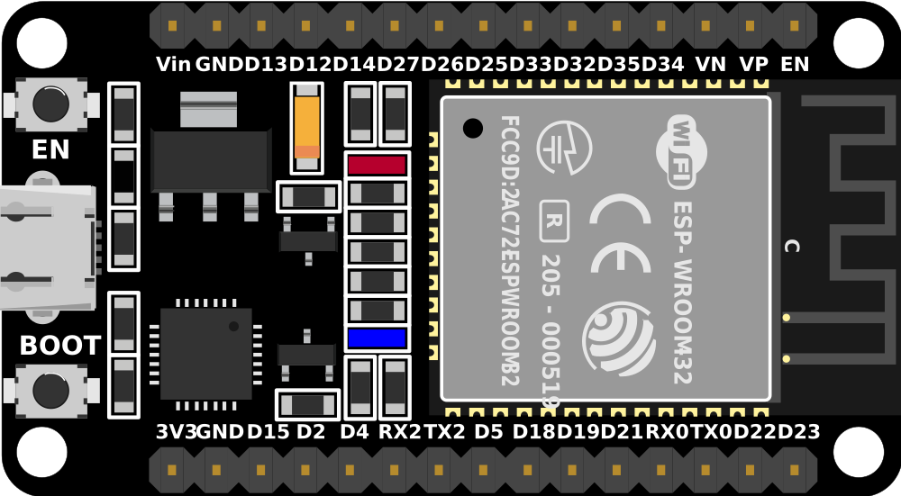
Pin Configuration and Descriptions
The ESP32 (30 pin) has the following pinout:
| Pin Number | Pin Name | Description |
|---|---|---|
| 1 | EN | Enable pin (active high) |
| 2 | IO0 | GPIO0, used for boot mode selection |
| 3 | IO1 (TX0) | GPIO1, UART0 TX |
| 4 | IO3 (RX0) | GPIO3, UART0 RX |
| 5 | IO4 | GPIO4, general-purpose I/O |
| 6 | IO5 | GPIO5, general-purpose I/O |
| 7 | GND | Ground |
| 8 | VIN | Power input (3.3V or 5V) |
| 9 | IO12 | GPIO12, general-purpose I/O |
| 10 | IO13 | GPIO13, general-purpose I/O |
| 11 | IO14 | GPIO14, general-purpose I/O |
| 12 | IO15 | GPIO15, general-purpose I/O |
| 13 | IO16 | GPIO16, general-purpose I/O |
| 14 | IO17 | GPIO17, general-purpose I/O |
| 15 | IO18 | GPIO18, general-purpose I/O |
| 16 | IO19 | GPIO19, general-purpose I/O |
| 17 | IO21 | GPIO21, general-purpose I/O |
| 18 | IO22 | GPIO22, general-purpose I/O |
| 19 | IO23 | GPIO23, general-purpose I/O |
| 20 | IO25 | GPIO25, general-purpose I/O |
| 21 | IO26 | GPIO26, general-purpose I/O |
| 22 | IO27 | GPIO27, general-purpose I/O |
| 23 | IO32 | GPIO32, ADC channel |
| 24 | IO33 | GPIO33, ADC channel |
| 25 | IO34 | GPIO34, ADC channel (input only) |
| 26 | IO35 | GPIO35, ADC channel (input only) |
| 27 | 3V3 | 3.3V power output |
| 28 | GND | Ground |
| 29 | IO36 | GPIO36, ADC channel (input only) |
| 30 | IO39 | GPIO39, ADC channel (input only) |
Usage Instructions
How to Use the ESP32 in a Circuit
Powering the ESP32:
- Connect the VIN pin to a 5V power source or use the USB port for power and programming.
- Ensure the GND pin is connected to the ground of your circuit.
Programming the ESP32:
- Use the Arduino IDE or ESP-IDF (Espressif IoT Development Framework) to program the ESP32.
- Install the necessary board definitions and drivers for the ESP32 in your development environment.
Connecting Peripherals:
- Use the GPIO pins to interface with sensors, actuators, and other devices.
- For analog inputs, connect sensors to ADC-capable pins (e.g., IO32, IO33).
Wi-Fi and Bluetooth Setup:
- Configure Wi-Fi and Bluetooth settings in your code to enable wireless communication.
Important Considerations and Best Practices
- Voltage Levels: The ESP32 operates at 3.3V logic levels. Avoid connecting 5V signals directly to GPIO pins.
- Boot Mode: GPIO0 must be pulled low during boot to enter programming mode.
- Power Supply: Use a stable power source to avoid unexpected resets or malfunctions.
- Heat Management: Ensure proper ventilation or heat dissipation for high-performance applications.
Example Code for Arduino UNO
Below is an example of how to connect the ESP32 to a Wi-Fi network using the Arduino IDE:
#include <WiFi.h> // Include the Wi-Fi library for ESP32

const char* ssid = "Your_SSID";       // Replace with your Wi-Fi network name
const char* password = "Your_Password"; // Replace with your Wi-Fi password

void setup() {
  Serial.begin(115200); // Initialize serial communication at 115200 baud
  delay(1000);          // Wait for a second to stabilize

  Serial.println("Connecting to Wi-Fi...");
  WiFi.begin(ssid, password); // Start Wi-Fi connection

  while (WiFi.status() != WL_CONNECTED) {
    delay(500); // Wait for connection
    Serial.print(".");
  }

  Serial.println("\nWi-Fi connected!");
  Serial.print("IP Address: ");
  Serial.println(WiFi.localIP()); // Print the assigned IP address
}

void loop() {
  // Add your main code here
}
Troubleshooting and FAQs
Common Issues and Solutions
ESP32 Not Connecting to Wi-Fi:
- Double-check the SSID and password in your code.
- Ensure the router is within range and supports 2.4 GHz Wi-Fi (ESP32 does not support 5 GHz).
ESP32 Not Detected by Computer:
- Verify that the correct drivers are installed for the ESP32.
- Use a high-quality USB cable and ensure it supports data transfer.
Random Resets or Instability:
- Check the power supply for stability and sufficient current (at least 500 mA).
- Avoid using GPIO pins connected to peripherals during boot (e.g., GPIO0, GPIO2).
Upload Fails with "Timed Out" Error:
- Ensure GPIO0 is pulled low during programming.
- Press and hold the "BOOT" button on the ESP32 while uploading the code.
FAQs
Q: Can I use the ESP32 with 5V logic devices?
A: No, the ESP32 operates at 3.3V logic levels. Use a level shifter to interface with 5V devices.
Q: How do I reset the ESP32?
A: Press the "EN" button on the board to reset the ESP32.
Q: Can the ESP32 run on battery power?
A: Yes, the ESP32 can be powered by a 3.7V LiPo battery connected to the VIN pin, but ensure proper voltage regulation.
Q: How many devices can the ESP32 connect to via Bluetooth?
A: The ESP32 supports up to 7 simultaneous Bluetooth connections in BLE mode.