
How to Use Header 6: Examples, Pinouts, and Specs
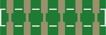
 Design with Header 6 in Cirkit Designer
Introduction
A Header 6 is a type of connector used in electronic circuits, typically featuring six pins arranged in a single or dual row. It is designed to facilitate the connection of various components or devices, enabling easy assembly, disassembly, and prototyping. Header 6 connectors are widely used in development boards, microcontroller projects, and PCB designs to establish reliable electrical connections.
Explore Projects Built with Header 6
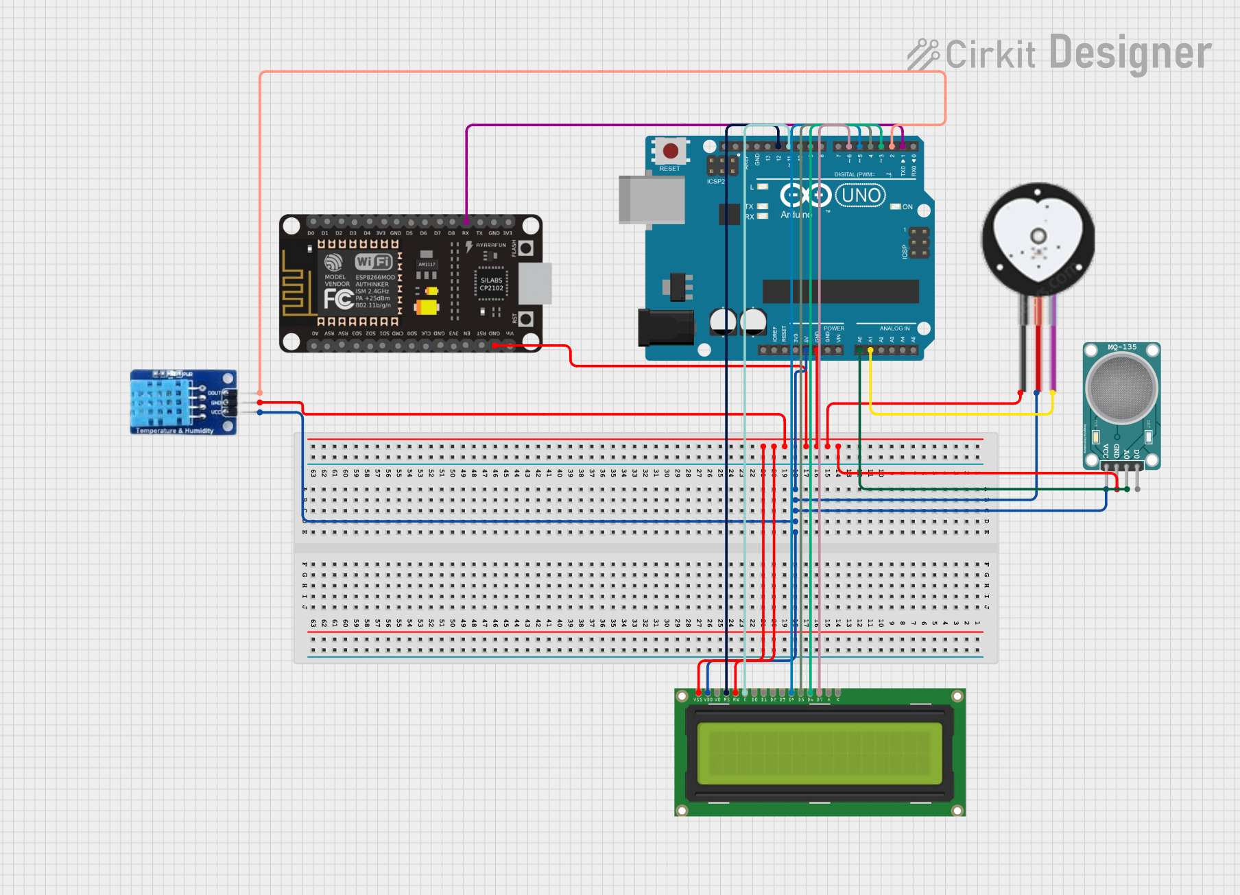 Open Project in Cirkit Designer
 Open Project in Cirkit Designer
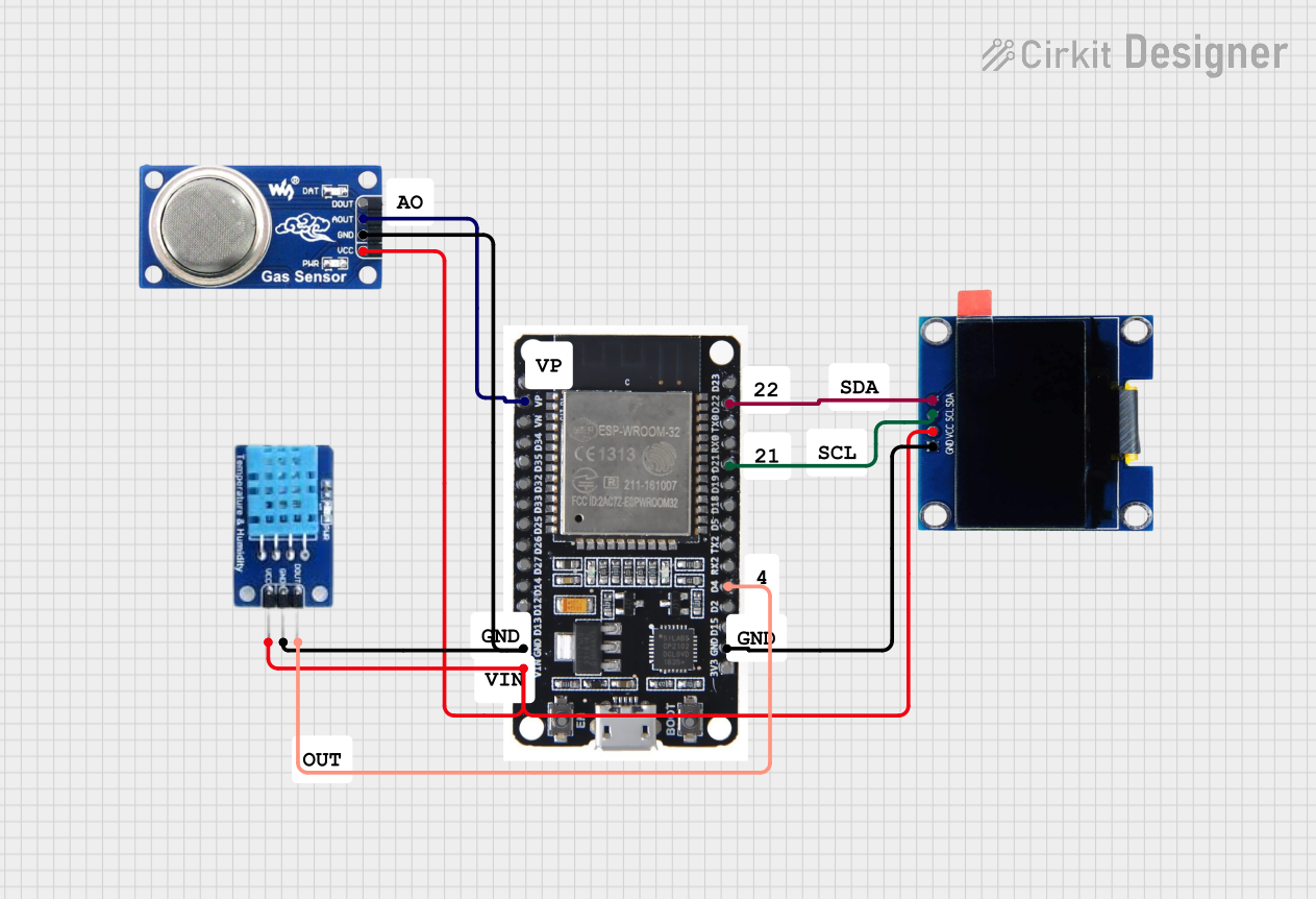 Open Project in Cirkit Designer
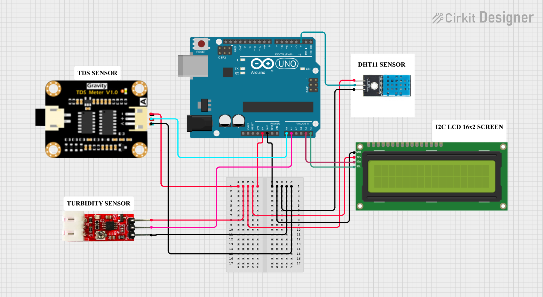 Open Project in Cirkit Designer
Explore Projects Built with Header 6
Open Project in Cirkit DesignerOpen Project in Cirkit DesignerOpen Project in Cirkit DesignerOpen Project in Cirkit DesignerCommon Applications and Use Cases
- Connecting sensors, modules, or peripherals to microcontrollers
- Prototyping circuits on breadboards or PCBs
- Establishing connections between stacked PCBs
- Interfacing with development boards like Arduino, Raspberry Pi, or ESP32
- Creating modular and easily replaceable circuit designs
Technical Specifications
Key Technical Details
- Number of Pins: 6
- Pin Pitch: 2.54 mm (standard spacing)
- Current Rating: Typically 1A per pin (varies by manufacturer)
- Voltage Rating: Up to 250V (varies by manufacturer)
- Operating Temperature: -40°C to +105°C (typical)
- Material:
- Pins: Tin-plated or gold-plated copper alloy
- Housing: Thermoplastic (UL94V-0 rated for flame resistance)
Pin Configuration and Descriptions
The Header 6 connector consists of six pins, which can be used for power, ground, data, or other signal connections. The pin configuration depends on the specific application. Below is an example of a typical pinout for a Header 6 used with an Arduino UNO:
| Pin Number | Description | Example Use Case |
|---|---|---|
| 1 | Ground (GND) | Common ground connection |
| 2 | VCC (Power) | Power supply (e.g., 5V) |
| 3 | Digital I/O Pin 1 | Data or control signal |
| 4 | Digital I/O Pin 2 | Data or control signal |
| 5 | Digital I/O Pin 3 | Data or control signal |
| 6 | Digital I/O Pin 4 | Data or control signal |
Note: The pinout may vary depending on the specific circuit or device. Always refer to the datasheet or schematic for your application.
Usage Instructions
How to Use the Component in a Circuit
Soldering:
- If using a PCB, solder the Header 6 connector into the designated holes, ensuring proper alignment and secure connections.
- For breadboard use, simply insert the pins into the breadboard holes.
Connecting Wires or Components:
- Use jumper wires or female connectors to attach components or modules to the Header 6 pins.
- Ensure that the connections match the intended pinout to avoid damage.
Interfacing with Microcontrollers:
- When connecting to a microcontroller like an Arduino UNO, align the Header 6 pins with the corresponding female headers on the board.
- Use the pinout table to map the connections correctly.
Important Considerations and Best Practices
- Avoid Overcurrent: Do not exceed the current rating of the pins to prevent overheating or damage.
- Check Pin Alignment: Ensure proper alignment when connecting to avoid short circuits or incorrect signals.
- Use Heat Shrink Tubing: For permanent installations, consider using heat shrink tubing to insulate exposed connections.
- Gold-Plated Pins: For high-reliability applications, use gold-plated Header 6 connectors to reduce oxidation and improve conductivity.
Example: Using Header 6 with Arduino UNO
Below is an example of how to connect a Header 6 to an Arduino UNO and control an LED:
// Example: Controlling an LED using a Header 6 connector
// Pin 3 of the Header 6 is connected to the LED's positive terminal
// Pin 1 (GND) is connected to the LED's negative terminal

const int ledPin = 3; // Header 6 Pin 3 connected to Arduino digital pin 3

void setup() {
  pinMode(ledPin, OUTPUT); // Set the LED pin as an output
}

void loop() {
  digitalWrite(ledPin, HIGH); // Turn the LED on
  delay(1000);               // Wait for 1 second
  digitalWrite(ledPin, LOW);  // Turn the LED off
  delay(1000);               // Wait for 1 second
}
Tip: Always double-check the connections before powering the circuit to avoid damaging components.
Troubleshooting and FAQs
Common Issues Users Might Face
Loose Connections:
- Problem: The Header 6 pins are not making proper contact with the mating connector.
- Solution: Ensure the pins are fully inserted and aligned. If using a breadboard, verify that the pins are not bent or damaged.
Incorrect Pinout:
- Problem: The circuit does not work as expected due to incorrect wiring.
- Solution: Double-check the pinout and ensure all connections match the intended design.
Overheating:
- Problem: The Header 6 connector becomes hot during operation.
- Solution: Verify that the current through the pins does not exceed the rated limit. Use thicker wires or additional pins for high-current applications.
Oxidation or Corrosion:
- Problem: Poor electrical contact due to oxidation on the pins.
- Solution: Use gold-plated Header 6 connectors for better durability and conductivity.
FAQs
Q: Can I use a Header 6 connector for high-frequency signals?
A: Yes, but ensure the connector and PCB layout are designed to minimize signal loss and interference.Q: Are Header 6 connectors reusable?
A: Yes, they are reusable, especially when used with breadboards or female connectors. However, repeated soldering and desoldering may degrade the pins.Q: Can I cut a longer header strip to create a Header 6?
A: Yes, you can cut a longer header strip to the desired length using a sharp tool, but ensure the cut edges are clean and free of burrs.
By following this documentation, you can effectively use a Header 6 connector in your electronic projects with confidence and reliability.