How to Use USB 2.0 Female Module: Examples, Pinouts, and Specs
Introduction
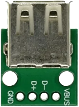
The USB 2.0 Female Module is a connector that allows USB devices to interface with a host system, such as a computer, microcontroller, or development board. It supports both data transfer and power supply capabilities, making it a versatile component for a wide range of electronic projects. This module is commonly used in applications such as USB device prototyping, power delivery, and communication between peripherals and host systems.
Explore Projects Built with USB 2.0 Female Module


Explore Projects Built with USB 2.0 Female Module
Common Applications and Use Cases
- Connecting USB peripherals (e.g., keyboards, mice, flash drives) to a host system.
- Powering small electronic devices via USB.
- Prototyping USB-based circuits and projects.
- Interfacing microcontrollers (e.g., Arduino) with USB devices.
- Building custom USB hubs or adapters.
Technical Specifications
The USB 2.0 Female Module is designed to meet the USB 2.0 standard, ensuring reliable data transfer and power delivery. Below are the key technical details:
General Specifications
- USB Standard: USB 2.0 (backward compatible with USB 1.1)
- Data Transfer Rate: Up to 480 Mbps (High-Speed)
- Power Supply: 5V DC (up to 500mA for standard USB 2.0)
- Connector Type: USB Type-A Female
- Operating Temperature: -20°C to 70°C
- Durability: Rated for 1,500+ insertion/removal cycles
Pin Configuration and Descriptions
The USB 2.0 Female Module has four pins, as described in the table below:
| Pin Number | Name | Description |
|---|---|---|
| 1 | VBUS | Provides 5V power supply to connected devices. |
| 2 | D- | Data line for differential signaling (negative). |
| 3 | D+ | Data line for differential signaling (positive). |
| 4 | GND | Ground connection for power and signal reference. |
Usage Instructions
How to Use the USB 2.0 Female Module in a Circuit
- Power Supply: Connect the VBUS pin to a 5V power source and the GND pin to the ground of your circuit.
- Data Lines: Connect the D+ and D- pins to the corresponding data lines of your microcontroller or USB host.
- Mounting: Secure the module to your PCB or project enclosure using screws or adhesive for stability.
- Testing: Verify the connections with a multimeter before powering the circuit to avoid short circuits.
Important Considerations and Best Practices
- Voltage Regulation: Ensure that the connected device does not draw more than 500mA unless the host supports higher current (e.g., USB 3.0 or dedicated power supply).
- Signal Integrity: Use short, shielded cables for data lines to minimize noise and signal degradation.
- ESD Protection: Add ESD protection diodes to the data lines to protect against electrostatic discharge.
- Pinout Verification: Double-check the pinout before connecting the module to avoid damaging your circuit or USB device.
Example: Connecting to an Arduino UNO
The USB 2.0 Female Module can be used to interface USB devices with an Arduino UNO. Below is an example of how to connect the module and read data from a USB device.
Circuit Diagram
- Connect the VBUS pin to the Arduino's 5V pin.
- Connect the GND pin to the Arduino's GND pin.
- Connect the D+ and D- pins to the appropriate data pins on a USB host shield or USB-to-serial converter.
Sample Code
#include <SoftwareSerial.h>

// Define RX and TX pins for USB communication
SoftwareSerial usbSerial(10, 11); // RX = pin 10, TX = pin 11

void setup() {
  Serial.begin(9600); // Initialize serial communication with the PC
  usbSerial.begin(9600); // Initialize USB communication
  Serial.println("USB 2.0 Female Module Test");
}

void loop() {
  // Check if data is available from the USB device
  if (usbSerial.available()) {
    char data = usbSerial.read(); // Read a byte from the USB device
    Serial.print("Received: ");
    Serial.println(data); // Print the received data to the Serial Monitor
  }
}
Note: This example assumes the use of a USB host shield or USB-to-serial converter to interface the USB 2.0 Female Module with the Arduino UNO.
Troubleshooting and FAQs
Common Issues and Solutions
No Power to Connected Device:
- Cause: Incorrect connection of the VBUS or GND pin.
- Solution: Verify the power connections and ensure the host system provides 5V.
Data Transfer Fails:
- Cause: Misconnection of D+ and D- pins or poor signal integrity.
- Solution: Check the data line connections and use shielded cables.
Device Not Recognized by Host:
- Cause: Unsupported device or missing USB driver.
- Solution: Ensure the device is compatible with the host and install the necessary drivers.
Overcurrent Protection Triggered:
- Cause: Connected device draws more current than allowed.
- Solution: Use a powered USB hub or ensure the device complies with USB 2.0 power limits.
FAQs
Q: Can this module be used with USB 3.0 devices?
- A: Yes, USB 3.0 devices are backward compatible with USB 2.0, but the data transfer rate will be limited to 480 Mbps.
Q: Is it possible to use this module for charging devices?
- A: Yes, the module can supply 5V power for charging, but ensure the current draw does not exceed 500mA.
Q: Do I need additional components to use this module with a microcontroller?
- A: For data communication, you may need a USB host shield or USB-to-serial converter, depending on your microcontroller.
Q: How do I protect the module from damage?
- A: Use ESD protection diodes on the data lines and avoid exceeding the rated voltage and current limits.