Cirkit Designer Logo
Cirkit Designer
Your all-in-one circuit design IDE
Home / 
Component Documentation

How to Use relay askes on/off: Examples, Pinouts, and Specs

Image of relay askes on/off
Cirkit Designer LogoDesign with relay askes on/off in Cirkit Designer

Introduction

A relay is an electrically operated switch that allows you to control high-power devices (e.g., motors, lights, or appliances) using low-power control signals. Relay modules are widely used in automation, home appliances, and industrial control systems. They provide electrical isolation between the control circuit and the high-power circuit, ensuring safety and reliability.

Common applications of relay modules include:

  • Home automation systems (e.g., controlling lights or fans remotely)
  • Industrial equipment control
  • Motor control circuits
  • Safety systems and alarms

Explore Projects Built with relay askes on/off

Use Cirkit Designer to design, explore, and prototype these projects online. Some projects support real-time simulation. Click "Open Project" to start designing instantly!
RF-Controlled Relay Switch with Indicator LEDs and Buzzer
Image of receiver: A project utilizing relay askes on/off in a practical application
This circuit features an RF receiver that controls a 12V relay, which in turn switches between two circuits: one with a green LED and another with a red LED and a buzzer, both protected by resistors. A rocker switch is used to supply power from a 9V battery to the RF receiver and the relay's coil. The relay's normally closed (NC) contact is connected to the green LED, while the normally open (NO) contact is connected to the red LED and the buzzer, indicating that the relay's state determines which of the two circuits is active.
Cirkit Designer LogoOpen Project in Cirkit Designer
LDR-Activated Relay Control for Dual Bulb Illumination
Image of automatic headlight control project : A project utilizing relay askes on/off in a practical application
This circuit appears to be a light-activated switch controlling two bulbs using a 5V relay, with an LDR (Light Dependent Resistor) as the sensor. The relay is powered by a 48V to 5V converter, which is switched on by a 12V battery through an SPST toggle switch. The LDR's output is connected to the relay's input, enabling the relay to switch the bulbs on or off based on the ambient light level detected by the LDR.
Cirkit Designer LogoOpen Project in Cirkit Designer
Arduino-Controlled Relay Switch for Bulb Illumination
Image of relay: A project utilizing relay askes on/off in a practical application
This circuit uses an Arduino UNO to control a 12V single-channel relay, which in turn switches two bulbs on and off alternately. The Arduino toggles the relay's input pin (D13) every second, causing one bulb to be connected to the normally closed (NC) contact and the other to the normally open (NO) contact, thus alternating their power states. This setup could be used for creating a simple blinking light system.
Cirkit Designer LogoOpen Project in Cirkit Designer
Arduino-Controlled Relay Switch for Bulb Illumination
Image of Interface One Channel Relay Module With Arduino: A project utilizing relay askes on/off in a practical application
This circuit uses an Arduino UNO to control a KF-301 relay, which in turn switches a bulb on and off. The relay is connected to the bulb and a socket, allowing the bulb to be powered when the relay is activated. The Arduino's code is set to toggle the relay every 3 seconds, using pin D6 to send the control signal, which operates the relay with inverted logic (LOW to activate, HIGH to deactivate).
Cirkit Designer LogoOpen Project in Cirkit Designer

Explore Projects Built with relay askes on/off

Use Cirkit Designer to design, explore, and prototype these projects online. Some projects support real-time simulation. Click "Open Project" to start designing instantly!
Image of receiver: A project utilizing relay askes on/off in a practical application
RF-Controlled Relay Switch with Indicator LEDs and Buzzer
This circuit features an RF receiver that controls a 12V relay, which in turn switches between two circuits: one with a green LED and another with a red LED and a buzzer, both protected by resistors. A rocker switch is used to supply power from a 9V battery to the RF receiver and the relay's coil. The relay's normally closed (NC) contact is connected to the green LED, while the normally open (NO) contact is connected to the red LED and the buzzer, indicating that the relay's state determines which of the two circuits is active.
Cirkit Designer LogoOpen Project in Cirkit Designer
Image of automatic headlight control project : A project utilizing relay askes on/off in a practical application
LDR-Activated Relay Control for Dual Bulb Illumination
This circuit appears to be a light-activated switch controlling two bulbs using a 5V relay, with an LDR (Light Dependent Resistor) as the sensor. The relay is powered by a 48V to 5V converter, which is switched on by a 12V battery through an SPST toggle switch. The LDR's output is connected to the relay's input, enabling the relay to switch the bulbs on or off based on the ambient light level detected by the LDR.
Cirkit Designer LogoOpen Project in Cirkit Designer
Image of relay: A project utilizing relay askes on/off in a practical application
Arduino-Controlled Relay Switch for Bulb Illumination
This circuit uses an Arduino UNO to control a 12V single-channel relay, which in turn switches two bulbs on and off alternately. The Arduino toggles the relay's input pin (D13) every second, causing one bulb to be connected to the normally closed (NC) contact and the other to the normally open (NO) contact, thus alternating their power states. This setup could be used for creating a simple blinking light system.
Cirkit Designer LogoOpen Project in Cirkit Designer
Image of Interface One Channel Relay Module With Arduino: A project utilizing relay askes on/off in a practical application
Arduino-Controlled Relay Switch for Bulb Illumination
This circuit uses an Arduino UNO to control a KF-301 relay, which in turn switches a bulb on and off. The relay is connected to the bulb and a socket, allowing the bulb to be powered when the relay is activated. The Arduino's code is set to toggle the relay every 3 seconds, using pin D6 to send the control signal, which operates the relay with inverted logic (LOW to activate, HIGH to deactivate).
Cirkit Designer LogoOpen Project in Cirkit Designer

Technical Specifications

Below are the key technical details for a standard single-channel relay module:

Parameter Value
Operating Voltage 5V DC
Trigger Voltage 3.3V to 5V DC
Maximum Load Voltage 250V AC / 30V DC
Maximum Load Current 10A
Relay Type SPDT (Single Pole Double Throw)
Isolation Optocoupler-based isolation
Dimensions ~50mm x 26mm x 18mm

Pin Configuration

The relay module typically has the following pins:

Pin Name Description
VCC Connect to the 5V power supply of the control circuit.
GND Connect to the ground of the control circuit.
IN Control signal input. A HIGH signal activates the relay, and a LOW signal deactivates it.
COM Common terminal for the relay switch.
NO Normally Open terminal. Connect the load here if you want it to be OFF by default.
NC Normally Closed terminal. Connect the load here if you want it to be ON by default.

Usage Instructions

How to Use the Relay Module in a Circuit

  1. Power the Relay Module: Connect the VCC pin to a 5V power source and the GND pin to the ground of your control circuit.
  2. Connect the Control Signal: Connect the IN pin to the control signal source (e.g., a microcontroller like Arduino UNO).
  3. Connect the Load:
    • Identify whether you want the load to be ON or OFF by default.
    • For an OFF-by-default configuration, connect the load to the NO (Normally Open) terminal and COM terminal.
    • For an ON-by-default configuration, connect the load to the NC (Normally Closed) terminal and COM terminal.
  4. Control the Relay: Send a HIGH signal to the IN pin to activate the relay and switch the load.

Important Considerations and Best Practices

  • Electrical Isolation: Ensure the control circuit and the high-power circuit are electrically isolated to prevent damage to sensitive components.
  • Flyback Diode: If you're controlling an inductive load (e.g., a motor), use a flyback diode across the load to protect the relay from voltage spikes.
  • Power Ratings: Do not exceed the relay's maximum voltage and current ratings to avoid damage or fire hazards.
  • Debouncing: If the relay is used in a rapidly switching application, consider implementing software or hardware debouncing to prevent erratic behavior.

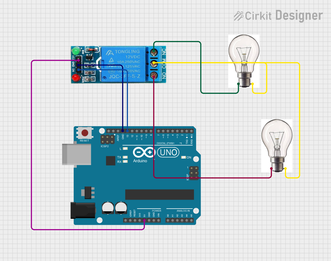
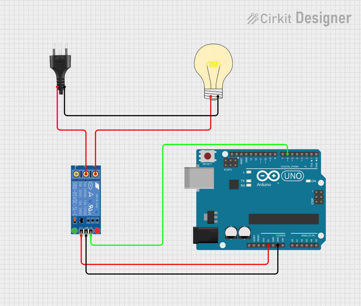
Example: Using a Relay Module with Arduino UNO

Below is an example of how to control a relay module using an Arduino UNO:

// Define the pin connected to the relay module
const int relayPin = 7;

void setup() {
  // Set the relay pin as an output
  pinMode(relayPin, OUTPUT);

  // Ensure the relay is OFF at startup
  digitalWrite(relayPin, LOW);
}

void loop() {
  // Turn the relay ON
  digitalWrite(relayPin, HIGH);
  delay(5000); // Keep the relay ON for 5 seconds

  // Turn the relay OFF
  digitalWrite(relayPin, LOW);
  delay(5000); // Keep the relay OFF for 5 seconds
}

Note: Replace relayPin with the actual pin number connected to the IN pin of the relay module.

Troubleshooting and FAQs

Common Issues and Solutions

  1. Relay Not Activating:

    • Cause: Insufficient voltage or current to the IN pin.
    • Solution: Ensure the control signal voltage is within the specified range (3.3V to 5V).
  2. Load Not Switching:

    • Cause: Incorrect wiring of the load to the relay terminals.
    • Solution: Double-check the connections to the NO, NC, and COM terminals.
  3. Relay Clicking Rapidly:

    • Cause: Noise or unstable control signal.
    • Solution: Use a pull-down resistor on the IN pin or implement software debouncing.
  4. Burnt Relay:

    • Cause: Exceeding the relay's voltage or current ratings.
    • Solution: Verify the load's power requirements and ensure they are within the relay's specifications.

FAQs

Q: Can I use a 3.3V microcontroller to control a 5V relay module?
A: Yes, most relay modules with optocoupler isolation can be triggered by 3.3V signals. However, verify the module's datasheet to confirm compatibility.

Q: Can I control multiple relays with one Arduino?
A: Yes, you can control multiple relays by connecting each relay's IN pin to a separate digital pin on the Arduino. Ensure the Arduino can supply enough current for all relays.

Q: Why is the relay module making a buzzing sound?
A: This could be due to insufficient power supply or a rapidly fluctuating control signal. Check the power source and stabilize the control signal.

Q: Is it safe to use a relay module for high-power appliances?
A: Yes, as long as the appliance's voltage and current ratings are within the relay's specifications. Always ensure proper insulation and safety precautions.