How to Use T-ETH-Lite ESP32: Examples, Pinouts, and Specs
Introduction
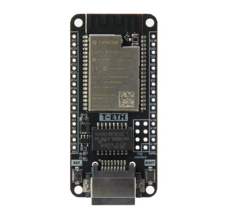
The T-ETH-Lite ESP32 is a compact development board designed and manufactured by LILYGO®. It features the powerful ESP32 microcontroller with integrated Ethernet capabilities, making it an excellent choice for IoT applications that require both Wi-Fi and wired network connectivity. This board is ideal for projects such as smart home systems, industrial automation, and networked sensors.
Explore Projects Built with T-ETH-Lite ESP32
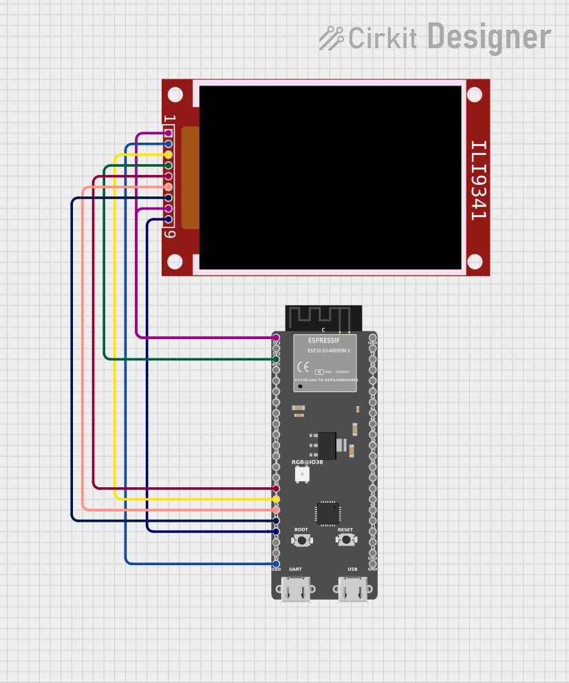
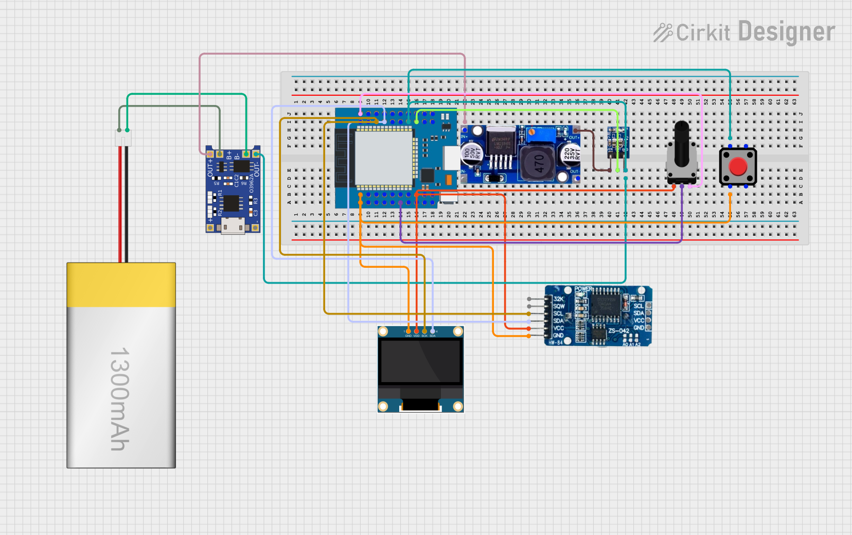
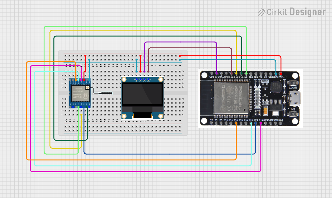

Explore Projects Built with T-ETH-Lite ESP32
Common Applications and Use Cases
- IoT devices requiring dual connectivity (Wi-Fi and Ethernet)
- Smart home automation systems
- Industrial monitoring and control
- Networked data loggers
- Prototyping Ethernet-enabled IoT solutions
Technical Specifications
The T-ETH-Lite ESP32 is built around the ESP32 microcontroller, which offers robust performance and versatile connectivity options. Below are the key technical details:
Key Technical Details
| Parameter | Specification |
|---|---|
| Microcontroller | ESP32 (dual-core, 32-bit Xtensa LX6) |
| Clock Speed | Up to 240 MHz |
| Flash Memory | 4 MB |
| SRAM | 520 KB |
| Connectivity | Wi-Fi 802.11 b/g/n, Ethernet |
| Ethernet Controller | LAN8720 |
| Operating Voltage | 3.3V |
| Input Voltage (VIN) | 5V (via USB-C) |
| GPIO Pins | 20+ |
| Communication Interfaces | UART, SPI, I2C, I2S, PWM, ADC, DAC |
| Dimensions | 50mm x 25mm |
Pin Configuration and Descriptions
The T-ETH-Lite ESP32 features a variety of pins for interfacing with peripherals. Below is the pinout description:
| Pin Name | Function | Description |
|---|---|---|
| VIN | Power Input | 5V input via USB-C or external power source |
| GND | Ground | Common ground |
| GPIO0 | General Purpose I/O | Used for boot mode selection |
| GPIO1 | UART TX | Serial communication (transmit) |
| GPIO3 | UART RX | Serial communication (receive) |
| GPIO12 | Ethernet MDC | Ethernet communication (clock signal) |
| GPIO13 | Ethernet MDIO | Ethernet communication (data signal) |
| GPIO16 | General Purpose I/O | Configurable GPIO |
| GPIO17 | General Purpose I/O | Configurable GPIO |
| GPIO18 | SPI CLK | SPI clock signal |
| GPIO19 | SPI MISO | SPI data input |
| GPIO23 | SPI MOSI | SPI data output |
| GPIO25 | DAC1 | Digital-to-Analog Converter output |
| GPIO26 | DAC2 | Digital-to-Analog Converter output |
| GPIO32 | ADC1 Channel 4 | Analog-to-Digital Converter input |
| GPIO33 | ADC1 Channel 5 | Analog-to-Digital Converter input |
Usage Instructions
The T-ETH-Lite ESP32 is versatile and easy to use in a variety of applications. Below are the steps and best practices for using this development board.
How to Use the Component in a Circuit
Powering the Board:
- Connect the board to a 5V power source via the USB-C port or the VIN pin.
- Ensure the power supply provides sufficient current (at least 500mA).
Programming the ESP32:
- Use the Arduino IDE or ESP-IDF (Espressif IoT Development Framework) to program the board.
- Select the correct board type (
ESP32 Dev Module) in the Arduino IDE. - Connect the board to your computer via USB-C and upload your code.
Ethernet Setup:
- Connect an Ethernet cable to the RJ45 port on the board.
- Use the LAN8720 Ethernet controller library to configure and manage Ethernet communication.
Wi-Fi Setup:
- Use the built-in Wi-Fi library in the ESP32 to connect to a wireless network.
- Configure the SSID and password in your code.
Important Considerations and Best Practices
- Voltage Levels: Ensure all connected peripherals operate at 3.3V logic levels to avoid damaging the board.
- Boot Mode: To enter boot mode for programming, hold down the
BOOTbutton while pressing theRESETbutton. - Ethernet Cable: Use a high-quality Ethernet cable to ensure reliable wired network connectivity.
- GPIO Usage: Avoid using GPIO pins reserved for Ethernet (e.g., GPIO12, GPIO13) for other purposes.
Example Code for Arduino IDE
Below is an example of how to configure the T-ETH-Lite ESP32 for Ethernet communication using the Arduino IDE:
#include <ETH.h>

// Define Ethernet configuration
#define ETH_CLK_MODE    ETH_CLOCK_GPIO17_OUT  // Clock mode for LAN8720
#define ETH_POWER_PIN   -1                    // No power pin used
#define ETH_TYPE        ETH_PHY_LAN8720       // Ethernet PHY type
#define ETH_ADDR        1                     // PHY address
#define ETH_MDC_PIN     23                    // MDC pin
#define ETH_MDIO_PIN    18                    // MDIO pin

void setup() {
  Serial.begin(115200);
  // Initialize Ethernet
  if (!ETH.begin(ETH_ADDR, ETH_POWER_PIN, ETH_MDC_PIN, ETH_MDIO_PIN, ETH_TYPE, ETH_CLK_MODE)) {
    Serial.println("Ethernet initialization failed!");
    return;
  }
  Serial.println("Ethernet initialized successfully!");
  Serial.print("IP Address: ");
  Serial.println(ETH.localIP());
}

void loop() {
  // Keep the Ethernet connection alive
  delay(1000);
}
Troubleshooting and FAQs
Common Issues Users Might Face
Ethernet Not Working:
- Ensure the Ethernet cable is securely connected to the RJ45 port.
- Verify that the correct pins (MDC, MDIO) are configured in your code.
Board Not Detected by Computer:
- Check the USB-C cable for proper data transfer capability.
- Ensure the correct drivers for the ESP32 are installed on your computer.
Wi-Fi Connection Fails:
- Double-check the SSID and password in your code.
- Ensure the Wi-Fi network is within range and not overloaded.
GPIO Pins Not Responding:
- Verify that the pins are not being used for Ethernet or other reserved functions.
- Check for short circuits or incorrect wiring.
Solutions and Tips for Troubleshooting
- Use a multimeter to check voltage levels on the power and GPIO pins.
- Update the ESP32 board package in the Arduino IDE to the latest version.
- Refer to the LILYGO® documentation for additional technical support and resources.
By following this documentation, you can effectively utilize the T-ETH-Lite ESP32 for your IoT and networking projects.