Cirkit Designer Logo
Cirkit Designer
Your all-in-one circuit design IDE
Home / 
Component Documentation

How to Use LM393: Examples, Pinouts, and Specs

Image of LM393
Cirkit Designer LogoDesign with LM393 in Cirkit Designer

Introduction

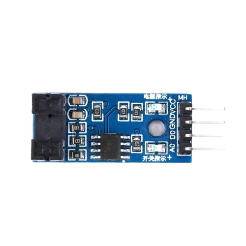
The LM393 is a widely used dual differential comparator integrated circuit, capable of comparing two input voltages and providing a digital output to indicate which input is higher. It is designed for use in level detection, battery monitoring, and other applications where a simple voltage comparison is required.

Explore Projects Built with LM393

Use Cirkit Designer to design, explore, and prototype these projects online. Some projects support real-time simulation. Click "Open Project" to start designing instantly!
ESP8266 NodeMCU with LM393 Comparator Interface
Image of LM393: A project utilizing LM393 in a practical application
This circuit features an ESP8266 NodeMCU microcontroller connected to an LM393 comparator. The NodeMCU's D3 pin is interfaced with the LM393's D0 output, suggesting that the microcontroller is configured to read a digital signal resulting from a comparison operation. The circuit is likely used for detecting a threshold voltage level or a specific condition that the LM393 is set up to monitor.
Cirkit Designer LogoOpen Project in Cirkit Designer
ESP32 with SIMCOM A7672s IoT Sensor Data Logger
Image of LM393 to LilygoSIM7000: A project utilizing LM393 in a practical application
This circuit integrates an ESP32 with SIMCOM A7672s module with an LM393 comparator for sensor data acquisition. The ESP32 is programmed to read a digital signal from the LM393's D0 output, corresponding to a threshold detection, and then sends this data to the Blynk Cloud using the SIMCOM A7672s module for remote monitoring. The LM393 is powered by the ESP32's 3.3V supply, and both share a common ground.
Cirkit Designer LogoOpen Project in Cirkit Designer
Battery-Powered LM393-Based Voltage Comparator Circuit with MOSFET Control
Image of cut off charger: A project utilizing LM393 in a practical application
This circuit is a power regulation and control system that uses an LM393 comparator to monitor voltage levels and control a MOSFET (IRFZ44N) for switching. It is powered by a 12V battery and a USB power source, and includes various resistors and capacitors for filtering and stabilization.
Cirkit Designer LogoOpen Project in Cirkit Designer
Solar-Powered Battery Charging and Monitoring System with TP4056 and 7-Segment Voltmeter
Image of CKT: A project utilizing LM393 in a practical application
This circuit is a solar-powered battery charging and monitoring system. It uses a TP4056 module to charge a Li-ion 18650 battery from solar cells and a DC generator, with multiple LEDs and a voltmeter to indicate the charging status and battery voltage. The circuit also includes transistors and resistors to control the LEDs and a bridge rectifier for AC to DC conversion.
Cirkit Designer LogoOpen Project in Cirkit Designer

Explore Projects Built with LM393

Use Cirkit Designer to design, explore, and prototype these projects online. Some projects support real-time simulation. Click "Open Project" to start designing instantly!
Image of LM393: A project utilizing LM393 in a practical application
ESP8266 NodeMCU with LM393 Comparator Interface
This circuit features an ESP8266 NodeMCU microcontroller connected to an LM393 comparator. The NodeMCU's D3 pin is interfaced with the LM393's D0 output, suggesting that the microcontroller is configured to read a digital signal resulting from a comparison operation. The circuit is likely used for detecting a threshold voltage level or a specific condition that the LM393 is set up to monitor.
Cirkit Designer LogoOpen Project in Cirkit Designer
Image of LM393 to LilygoSIM7000: A project utilizing LM393 in a practical application
ESP32 with SIMCOM A7672s IoT Sensor Data Logger
This circuit integrates an ESP32 with SIMCOM A7672s module with an LM393 comparator for sensor data acquisition. The ESP32 is programmed to read a digital signal from the LM393's D0 output, corresponding to a threshold detection, and then sends this data to the Blynk Cloud using the SIMCOM A7672s module for remote monitoring. The LM393 is powered by the ESP32's 3.3V supply, and both share a common ground.
Cirkit Designer LogoOpen Project in Cirkit Designer
Image of cut off charger: A project utilizing LM393 in a practical application
Battery-Powered LM393-Based Voltage Comparator Circuit with MOSFET Control
This circuit is a power regulation and control system that uses an LM393 comparator to monitor voltage levels and control a MOSFET (IRFZ44N) for switching. It is powered by a 12V battery and a USB power source, and includes various resistors and capacitors for filtering and stabilization.
Cirkit Designer LogoOpen Project in Cirkit Designer
Image of CKT: A project utilizing LM393 in a practical application
Solar-Powered Battery Charging and Monitoring System with TP4056 and 7-Segment Voltmeter
This circuit is a solar-powered battery charging and monitoring system. It uses a TP4056 module to charge a Li-ion 18650 battery from solar cells and a DC generator, with multiple LEDs and a voltmeter to indicate the charging status and battery voltage. The circuit also includes transistors and resistors to control the LEDs and a bridge rectifier for AC to DC conversion.
Cirkit Designer LogoOpen Project in Cirkit Designer

Common Applications and Use Cases

  • Voltage level detection
  • Battery chargers
  • Window comparators
  • Relay drivers
  • Simple analog to digital converters
  • Motor control circuits

Technical Specifications

Key Technical Details

  • Supply Voltage Range: 2.0V to 36V, or ±1.0V to ±18V
  • Input Bias Current: 25 nA (typical)
  • Input Offset Current: ±5 nA (typical)
  • Offset Voltage: ±1 mV (typical)
  • Supply Current: 0.8 mA (typical)
  • Response Time: 1.3 µs (typical)
  • Operating Temperature Range: 0°C to +70°C

Pin Configuration and Descriptions

Pin Number Name Description
1 OUT1 Output of comparator 1
2 IN1- Inverting input of comparator 1
3 IN1+ Non-inverting input of comparator 1
4 GND Ground (0V) reference
5 IN2+ Non-inverting input of comparator 2
6 IN2- Inverting input of comparator 2
7 OUT2 Output of comparator 2
8 VCC Positive supply voltage

Usage Instructions

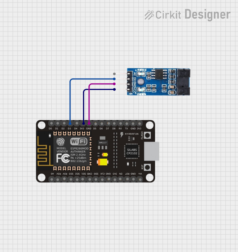
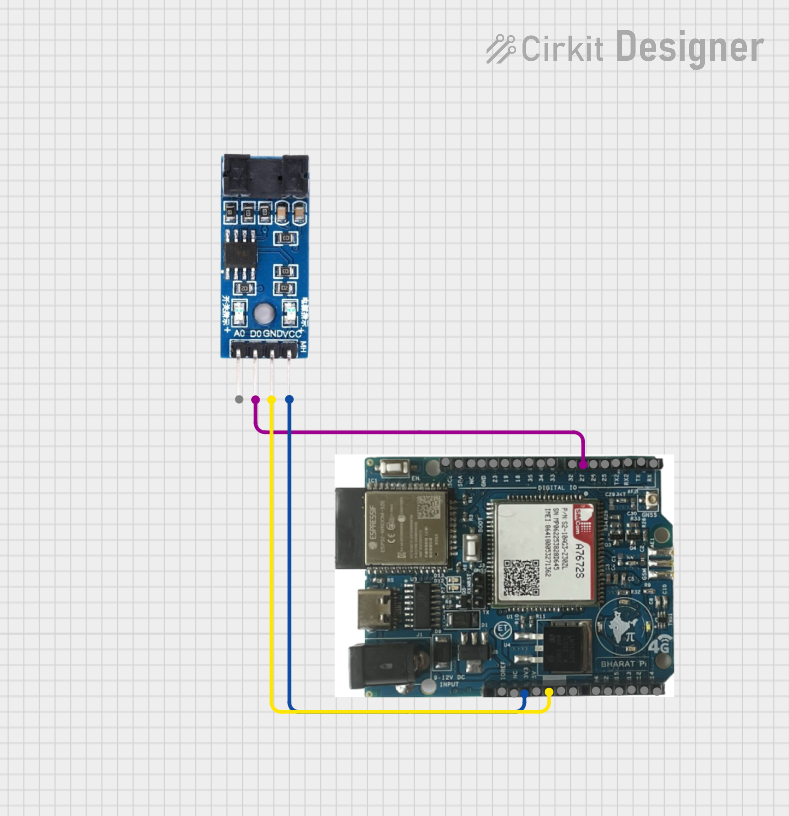
How to Use the LM393 in a Circuit

  1. Connect the VCC pin to a positive supply voltage within the specified range.
  2. Connect the GND pin to the ground of the power supply.
  3. Apply the reference voltage to the non-inverting input (IN1+ or IN2+).
  4. Apply the variable voltage to be compared to the inverting input (IN1- or IN2-).
  5. Connect the output (OUT1 or OUT2) to the digital input of a microcontroller or use it to drive a relay or an LED with appropriate current limiting.

Important Considerations and Best Practices

  • Always ensure that the supply voltage does not exceed the maximum rating.
  • Use bypass capacitors near the power supply pins to filter out noise and provide a stable operation.
  • Avoid applying voltages to the input pins that are outside the range of the power supply rails.
  • The outputs are open-collector, which means they require a pull-up resistor to the supply voltage to function correctly.

Example Circuit with Arduino UNO

// Example code for using LM393 with Arduino UNO

const int comparatorOutputPin = 2; // Connect to OUT1 or OUT2 of LM393
const int ledPin = 13; // Onboard LED

void setup() {
  pinMode(comparatorOutputPin, INPUT);
  pinMode(ledPin, OUTPUT);
}

void loop() {
  int comparatorState = digitalRead(comparatorOutputPin);
  if (comparatorState == HIGH) {
    // Voltage at IN1- or IN2- is higher than IN1+ or IN2+
    digitalWrite(ledPin, HIGH);
  } else {
    // Voltage at IN1+ or IN2+ is higher than IN1- or IN2-
    digitalWrite(ledPin, LOW);
  }
}

Troubleshooting and FAQs

Common Issues

  • No Output Signal: Ensure that the power supply is connected correctly and the input voltages are within the specified range.
  • Output Always High or Low: Check the input voltages and the connection of the pull-up resistor on the output pin.
  • Erratic Behavior: Place a bypass capacitor near the power supply pins to filter out noise.

Solutions and Tips for Troubleshooting

  • Verify the orientation of the LM393 in the circuit.
  • Use a multimeter to check the voltages at the input pins.
  • Ensure that the pull-up resistor value is appropriate for the supply voltage and the load connected to the output.

FAQs

Q: Can the LM393 be used with a single supply voltage? A: Yes, the LM393 can operate with a single supply voltage ranging from 2.0V to 36V.

Q: What is the purpose of the pull-up resistor on the output? A: The LM393 has an open-collector output, which requires an external pull-up resistor to provide a high level when the output transistor is off.

Q: Can the LM393 outputs sink current? A: Yes, the outputs can sink current, but the maximum current should not exceed the specified limit in the datasheet.

Q: Is the LM393 suitable for high-speed applications? A: The LM393 has a typical response time of 1.3 µs, which may be suitable for some high-speed applications, but there are faster comparators available for very high-speed needs.

Note: The manufacturer part ID "WPSE347" and the claim that Arduino is the manufacturer of the LM393 are incorrect. The LM393 is a generic part manufactured by various companies, and Arduino does not manufacture this component. The part ID provided does not correspond to a known manufacturer's part number for the LM393. Always refer to the datasheet from the specific manufacturer of your component for the most accurate information.