How to Use Voltage & current sensor INA219 breakout: Examples, Pinouts, and Specs
Introduction
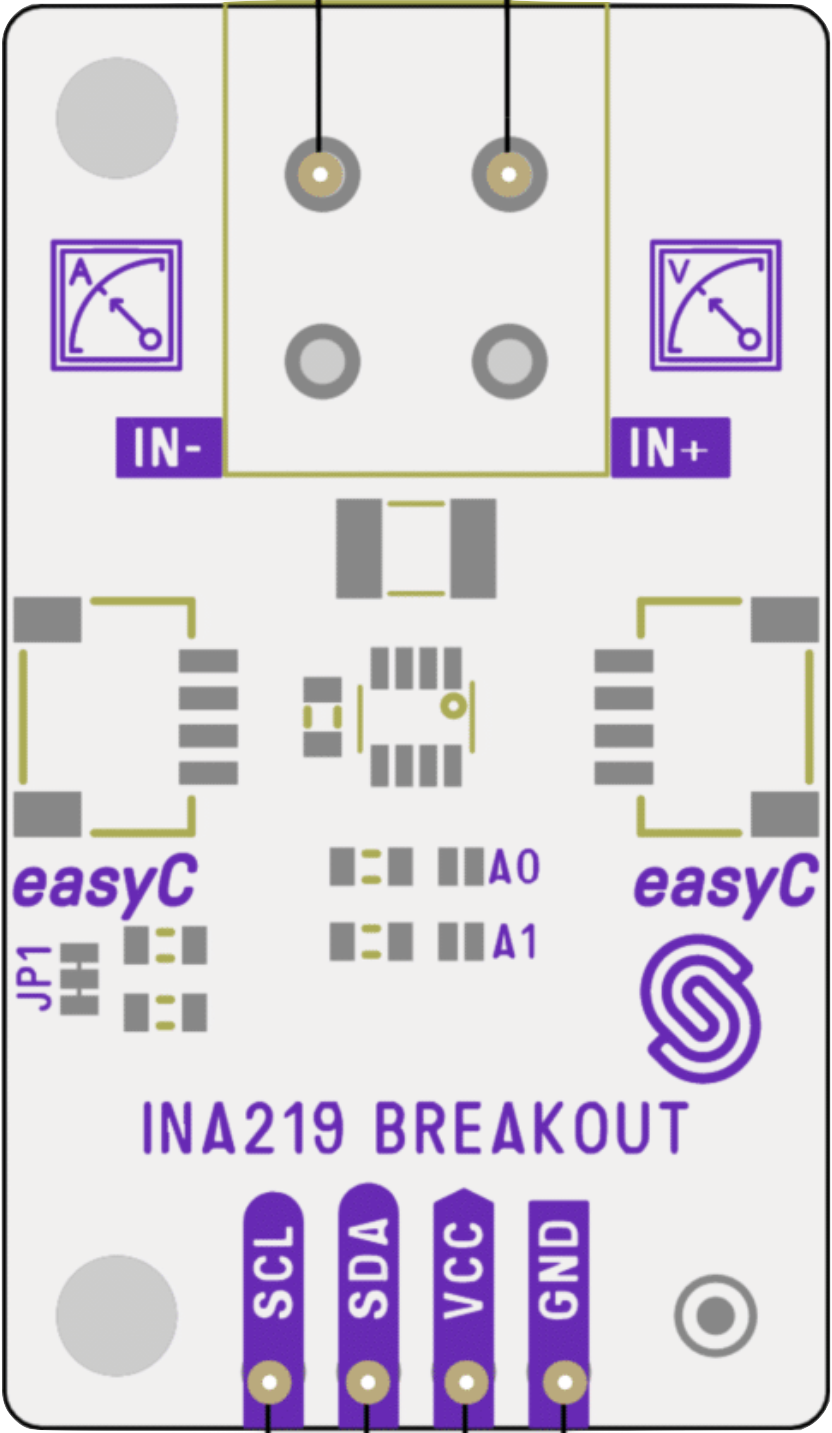
The Voltage & Current Sensor INA219 Breakout by Soldered is a high-side current sensor designed to measure voltage, current, and power in a circuit. It features the INA219 chip, which provides precise measurements and communicates via the I2C protocol. This breakout board is ideal for applications requiring real-time power monitoring, such as battery-powered devices, solar power systems, and energy-efficient designs.
Explore Projects Built with Voltage & current sensor INA219 breakout


Explore Projects Built with Voltage & current sensor INA219 breakout
Common Applications
- Monitoring power consumption in IoT devices
- Battery management systems
- Solar panel performance tracking
- Robotics and motor control systems
- General-purpose current and voltage measurement in electronics projects
Technical Specifications
The following table outlines the key technical details of the INA219 breakout board:
| Parameter | Value |
|---|---|
| Operating Voltage | 3.0V to 5.5V |
| Current Measurement Range | ±3.2A (default shunt resistor) |
| Voltage Measurement Range | 0V to 26V |
| Communication Interface | I2C |
| Default I2C Address | 0x40 |
| Resolution | 12-bit ADC |
| Shunt Resistor Value | 0.1Ω (pre-installed) |
| Power Consumption | ~1mA |
| Dimensions | 20mm x 20mm |
Pin Configuration
The INA219 breakout board has the following pin layout:
| Pin | Name | Description |
|---|---|---|
| 1 | VIN+ | Positive input for current measurement (connect to the high side of the load). |
| 2 | VIN- | Negative input for current measurement (connect to the low side of the load). |
| 3 | GND | Ground reference for the breakout board. |
| 4 | VCC | Power supply input (3.0V to 5.5V). |
| 5 | SDA | I2C data line for communication. |
| 6 | SCL | I2C clock line for communication. |
Usage Instructions
How to Use the INA219 Breakout in a Circuit
- Power the Board: Connect the
VCCpin to a 3.3V or 5V power source and theGNDpin to the ground of your circuit. - Connect the Load:
- Attach the
VIN+pin to the positive side of the load. - Attach the
VIN-pin to the negative side of the load.
- Attach the
- I2C Communication:
- Connect the
SDApin to the I2C data line of your microcontroller. - Connect the
SCLpin to the I2C clock line of your microcontroller.
- Connect the
- Install Required Libraries: If using an Arduino, install the Adafruit INA219 library from the Arduino Library Manager.
- Write Code: Use the library to initialize the sensor, read voltage, current, and power values, and display them.
Important Considerations
- Ensure the load current does not exceed the maximum measurable range of ±3.2A (with the default 0.1Ω shunt resistor).
- If higher currents need to be measured, replace the shunt resistor with a lower value and adjust the calculations in the code accordingly.
- Keep I2C lines (SDA and SCL) as short as possible to avoid communication issues.
- Use pull-up resistors on the I2C lines if your microcontroller does not have internal pull-ups enabled.
Example Arduino Code
Below is an example Arduino sketch to read voltage, current, and power using the INA219 breakout:
#include <Wire.h>
#include <Adafruit_INA219.h>

// Create an instance of the INA219 sensor
Adafruit_INA219 ina219;

void setup() {
  Serial.begin(9600); // Initialize serial communication at 9600 baud
  while (!Serial) {
    delay(10); // Wait for the serial monitor to open
  }

  // Initialize the INA219 sensor
  if (!ina219.begin()) {
    Serial.println("Failed to find INA219 chip");
    while (1) {
      delay(10); // Halt execution if the sensor is not detected
    }
  }
  Serial.println("INA219 sensor initialized successfully!");
}

void loop() {
  float shuntVoltage = ina219.getShuntVoltage_mV(); // Read shunt voltage in mV
  float busVoltage = ina219.getBusVoltage_V();      // Read bus voltage in V
  float current_mA = ina219.getCurrent_mA();        // Read current in mA
  float power_mW = ina219.getPower_mW();            // Read power in mW

  // Print the measurements to the serial monitor
  Serial.print("Bus Voltage: ");
  Serial.print(busVoltage);
  Serial.println(" V");

  Serial.print("Shunt Voltage: ");
  Serial.print(shuntVoltage);
  Serial.println(" mV");

  Serial.print("Current: ");
  Serial.print(current_mA);
  Serial.println(" mA");

  Serial.print("Power: ");
  Serial.print(power_mW);
  Serial.println(" mW");

  Serial.println("-----------------------------------");
  delay(1000); // Wait 1 second before taking the next reading
}
Troubleshooting and FAQs
Common Issues
No Communication with the Sensor:
- Ensure the I2C address (default:
0x40) matches the address in your code. - Check the connections for
SDAandSCLpins. - Verify that pull-up resistors are present on the I2C lines if required.
- Ensure the I2C address (default:
Incorrect Readings:
- Confirm that the load current is within the measurable range of the sensor.
- Check for loose or incorrect connections on the
VIN+andVIN-pins. - Ensure the shunt resistor value matches the default or is correctly configured in the code.
Sensor Not Detected:
- Verify that the
VCCandGNDpins are properly connected to the power supply. - Use an I2C scanner sketch to confirm the sensor's address.
- Verify that the
FAQs
Q: Can the INA219 measure negative currents?
A: Yes, the INA219 can measure bidirectional currents. However, you may need to configure the sensor for this mode in your code.
Q: How can I measure higher currents?
A: Replace the default 0.1Ω shunt resistor with a lower value (e.g., 0.01Ω) to increase the measurable current range. Update the calibration settings in your code accordingly.
Q: What is the maximum voltage the INA219 can measure?
A: The INA219 can measure up to 26V on the bus voltage line. Ensure the voltage does not exceed this limit to avoid damage.
Q: Can I use the INA219 with a 3.3V microcontroller?
A: Yes, the INA219 is compatible with both 3.3V and 5V systems. Ensure the VCC pin is connected to the appropriate voltage source.