How to Use LILYGO T-RADAR: Examples, Pinouts, and Specs
Introduction
The LILYGO T-RADAR (V1.0) is a compact and versatile radar sensor module designed for motion detection and distance measurement. It leverages advanced millimeter-wave radar technology to deliver precise and reliable sensing capabilities. The module is ideal for applications such as smart home automation, robotics, security systems, and IoT projects. Its small form factor and low power consumption make it a perfect choice for embedded systems and portable devices.
Explore Projects Built with LILYGO T-RADAR


Explore Projects Built with LILYGO T-RADAR
Common Applications
- Motion detection in smart home devices (e.g., lighting control, security systems)
- Distance measurement in robotics and automation
- Presence detection in IoT devices
- Gesture recognition for touchless control systems
Technical Specifications
The following table outlines the key technical specifications of the LILYGO T-RADAR module:
| Parameter | Specification |
|---|---|
| Operating Voltage | 3.3V - 5V DC |
| Operating Current | < 100mA |
| Frequency Band | 24 GHz |
| Detection Range | 0.5m to 10m |
| Detection Angle | ±60° |
| Communication Interface | UART (default baud rate: 115200 bps) |
| Operating Temperature | -20°C to 60°C |
| Dimensions | 25mm x 25mm |
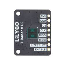
Pin Configuration
The LILYGO T-RADAR module has a simple pinout, as shown in the table below:
| Pin Name | Description |
|---|---|
| VCC | Power supply input (3.3V - 5V) |
| GND | Ground |
| TX | UART Transmit pin (data output) |
| RX | UART Receive pin (data input) |
| EN | Enable pin (active HIGH to enable the module) |
Usage Instructions
Connecting the LILYGO T-RADAR to a Circuit
- Power Supply: Connect the
VCCpin to a 3.3V or 5V power source and theGNDpin to ground. - UART Communication: Connect the
TXpin of the module to the RX pin of your microcontroller (e.g., Arduino UNO) and theRXpin of the module to the TX pin of the microcontroller. - Enable the Module: Ensure the
ENpin is pulled HIGH to activate the module. You can connect it directly toVCCor control it via a GPIO pin.
Important Considerations
- Power Supply: Use a stable power source to avoid noise or fluctuations that may affect the radar's performance.
- Placement: Avoid placing the module near metal objects or other RF-emitting devices to minimize interference.
- Detection Range: Ensure the module is positioned within its specified detection range (0.5m to 10m) for optimal performance.
Example Code for Arduino UNO
Below is an example Arduino sketch to interface with the LILYGO T-RADAR module and read motion detection data via UART:
// Example code to interface with LILYGO T-RADAR using Arduino UNO
// This code reads data from the radar module and prints it to the Serial Monitor.

#include <SoftwareSerial.h>

// Define the RX and TX pins for SoftwareSerial
#define RADAR_RX 2  // Connect to T-RADAR TX pin
#define RADAR_TX 3  // Connect to T-RADAR RX pin

// Initialize SoftwareSerial for communication with the radar module
SoftwareSerial radarSerial(RADAR_RX, RADAR_TX);

void setup() {
  // Start the hardware serial communication for debugging
  Serial.begin(115200);
  // Start the software serial communication with the radar module
  radarSerial.begin(115200);

  Serial.println("LILYGO T-RADAR Module Initialized");
}

void loop() {
  // Check if data is available from the radar module
  if (radarSerial.available()) {
    // Read and print the data from the radar module
    String radarData = radarSerial.readStringUntil('\n');
    Serial.println("Radar Data: " + radarData);
  }

  // Add a small delay to avoid flooding the Serial Monitor
  delay(100);
}
Notes:
- Ensure the
SoftwareSeriallibrary is used if the Arduino UNO's hardware UART is already in use. - The radar module outputs data in a specific format. Refer to the manufacturer's datasheet for details on parsing the data.
Troubleshooting and FAQs
Common Issues
No Data Received from the Module
- Solution: Verify the UART connections (TX and RX) between the module and the microcontroller. Ensure the baud rate is set to 115200 bps in your code.
Inconsistent Detection Results
- Solution: Check for environmental factors such as metal objects or RF interference. Ensure the module is within its specified detection range and angle.
Module Not Powering On
- Solution: Confirm that the
VCCandGNDpins are properly connected. Ensure theENpin is pulled HIGH.
- Solution: Confirm that the
Data Format is Unreadable
- Solution: Refer to the LILYGO T-RADAR datasheet for the correct data format and parsing instructions.
Tips for Troubleshooting
- Use a multimeter to verify the voltage levels on the
VCCandENpins. - Test the module in a controlled environment to rule out external interference.
- If using an Arduino, ensure the
SoftwareSeriallibrary is correctly configured and not conflicting with other peripherals.
By following this documentation, you can effectively integrate the LILYGO T-RADAR module into your projects and troubleshoot common issues with ease.