How to Use MCP2515: Examples, Pinouts, and Specs
Introduction
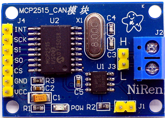
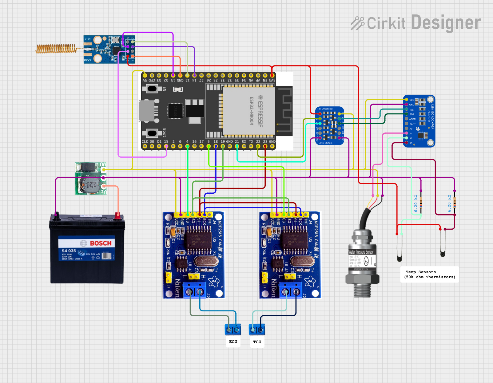
The MCP2515 is a robust, standalone Controller Area Network (CAN) controller that adheres to the CAN specification version 2.0B. It is a highly flexible and capable device designed for high-speed automotive and industrial communication networks. The MCP2515 module interfaces with microcontrollers (MCUs) via the Serial Peripheral Interface (SPI), allowing for the implementation of CAN communication with minimal overhead for the MCU. Common applications include automotive systems, industrial automation, smart home networks, and other environments where a reliable data bus is required to connect multiple microcontrollers and devices.
Explore Projects Built with MCP2515

Explore Projects Built with MCP2515
Technical Specifications
Key Technical Details
- Operating Voltage: 2.7V to 5.5V
- Temperature Range: -40°C to +125°C
- CAN Controller: Implements CAN V2.0B at up to 1 Mb/s
- Oscillator: External crystal oscillator can be connected
- Interfaces: SPI for communication with MCUs
Pin Configuration and Descriptions
| Pin Number | Pin Name | Description |
|---|---|---|
| 1 | VDD | Power supply input (2.7V to 5.5V) |
| 2 | VSS | Ground reference for power supply |
| 3 | OSC1 | Connection to crystal oscillator or external clock |
| 4 | OSC2 | Connection to crystal oscillator |
| 5 | RESET | Active-low reset input |
| 6 | CS | SPI Chip Select (active low) |
| 7 | SO | SPI Serial Output (MISO) |
| 8 | SI | SPI Serial Input (MOSI) |
| 9 | SCK | SPI Clock Input |
| 10 | INT | Interrupt output (active low) |
| 11 | TX0RTS | Transmit buffer 0 request-to-send (optional GPIO) |
| 12 | TX1RTS | Transmit buffer 1 request-to-send (optional GPIO) |
| 13 | TX2RTS | Transmit buffer 2 request-to-send (optional GPIO) |
| 14 | RX0BF | Receive buffer 0 interrupt flag (optional GPIO) |
| 15 | RX1BF | Receive buffer 1 interrupt flag (optional GPIO) |
| 16 | TXCAN | CAN transmit output |
| 17 | RXCAN | CAN receive input |
| 18 | STBY | Standby control input (optional) |
Usage Instructions
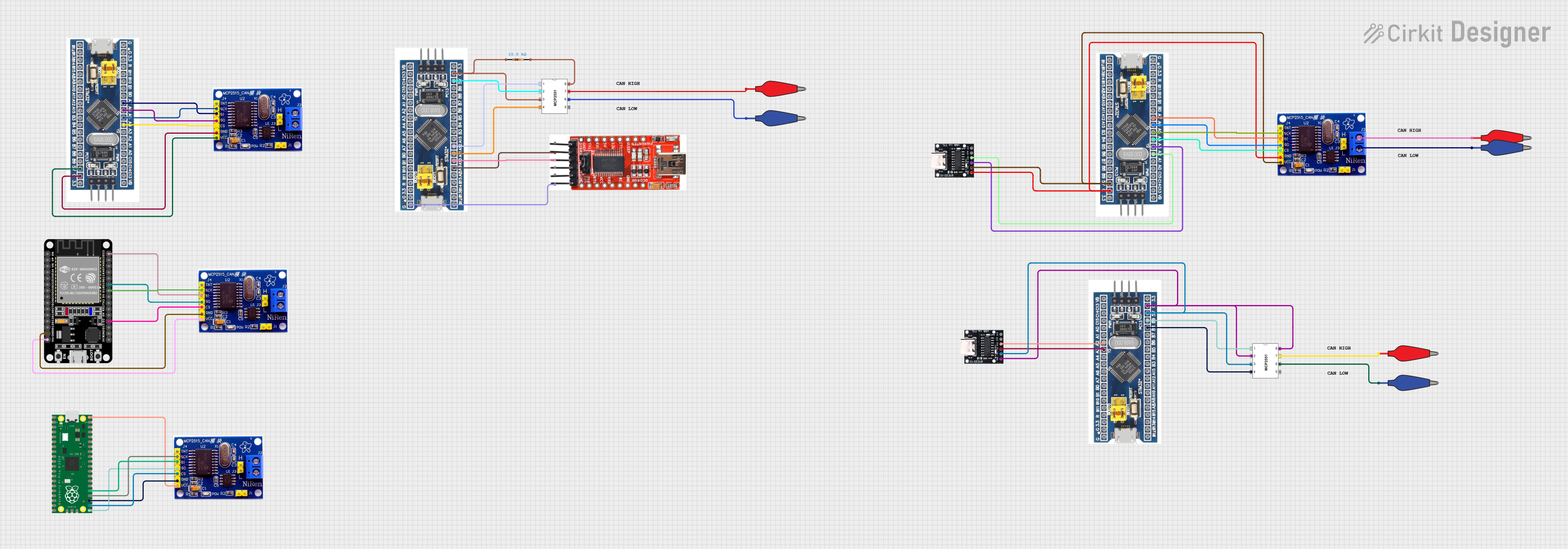
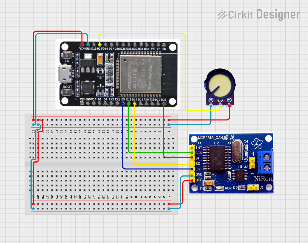
Interfacing with a Microcontroller
To use the MCP2515 with a microcontroller such as an Arduino UNO, the following connections are required:
- Connect VDD to the 5V output on the Arduino.
- Connect VSS to the GND on the Arduino.
- Connect the SPI pins (CS, SO, SI, SCK) to the corresponding SPI pins on the Arduino.
- Connect the INT pin to an external interrupt-capable pin on the Arduino for interrupt-driven communication.
Initialization and Configuration
Before sending or receiving CAN messages, the MCP2515 must be properly initialized and configured. This includes setting up the bit rate, configuring the masks and filters for message acceptance, and enabling interrupts if necessary.
Sending CAN Messages
To send a CAN message, the data must be loaded into one of the transmit buffers, and a transmission request must be initiated. The MCP2515 will handle the arbitration and transmission of the message onto the CAN bus.
Receiving CAN Messages
Received messages will be stored in one of the receive buffers. The microcontroller can retrieve the message by reading from the MCP2515 via SPI. Using interrupts can improve efficiency by notifying the microcontroller when a new message has arrived.
Best Practices
- Use proper termination resistors on the CAN bus to ensure signal integrity.
- Ensure that the SPI communication between the microcontroller and MCP2515 is reliable, with appropriate clock speeds and signal levels.
- Configure the MCP2515's filters and masks to only accept relevant messages, reducing the processing overhead for the microcontroller.
Troubleshooting and FAQs
Common Issues
- CAN Bus Not Functioning: Ensure that the bus is properly terminated and that there are no short circuits or open connections.
- No Communication with MCP2515: Check the SPI connections and ensure that the correct SPI mode and clock speed are used.
- Messages Not Being Received: Verify the configuration of masks and filters, and ensure that the MCP2515 is not in a bus-off state due to errors.
Solutions and Tips
- If the MCP2515 is not responding, perform a hardware reset by toggling the RESET pin.
- Use an oscilloscope to check the signal integrity on the SPI bus and the CAN bus.
- Ensure that the crystal oscillator is functioning correctly if an external clock source is used.
FAQs
Q: Can the MCP2515 be used with 3.3V systems? A: Yes, the MCP2515 can operate at voltages as low as 2.7V.
Q: How many receive and transmit buffers does the MCP2515 have? A: The MCP2515 has two receive buffers and three transmit buffers.
Q: What is the maximum speed of the CAN bus with the MCP2515? A: The MCP2515 can handle CAN bus speeds up to 1 Mb/s.
Q: Does the MCP2515 support listen-only mode? A: Yes, the MCP2515 has a listen-only mode for monitoring CAN traffic without affecting the bus.
Example Code for Arduino UNO
Below is an example of initializing the MCP2515 with an Arduino UNO. This code assumes the use of an MCP2515 library for Arduino, which provides higher-level functions for interacting with the device.
#include <mcp2515.h>

MCP2515 mcp2515(10); // CS pin on Arduino is connected to pin 10

void setup() {
  Serial.begin(9600);

  // Initialize SPI communication with the MCP2515
  mcp2515.reset();
  mcp2515.setBitrate(CAN_500KBPS, MCP_8MHZ);
  mcp2515.setNormalMode();

  // More initialization code as needed...
}

void loop() {
  // Code to send and receive CAN messages...
}
Please note that this is a simplified example. For a complete implementation, additional code is required to handle message sending, receiving, and error checking. Always refer to the library's documentation for detailed usage instructions.