How to Use Adafruit Raspberry Pi Perma Proto Half: Examples, Pinouts, and Specs
Introduction
The Adafruit Raspberry Pi Perma Proto Half is a versatile prototyping board tailored for the Raspberry Pi ecosystem. It is designed to offer a solderable solution for permanent projects, combining the flexibility of a breadboard with the durability of a printed circuit board (PCB). This board is ideal for hobbyists, educators, and professionals who wish to transition their temporary breadboarded circuits to a more stable and permanent setup without the complexity of designing a custom PCB.
Explore Projects Built with Adafruit Raspberry Pi Perma Proto Half

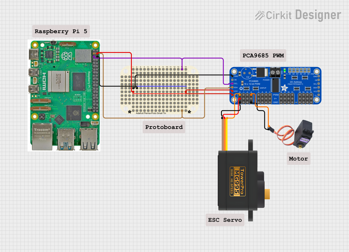
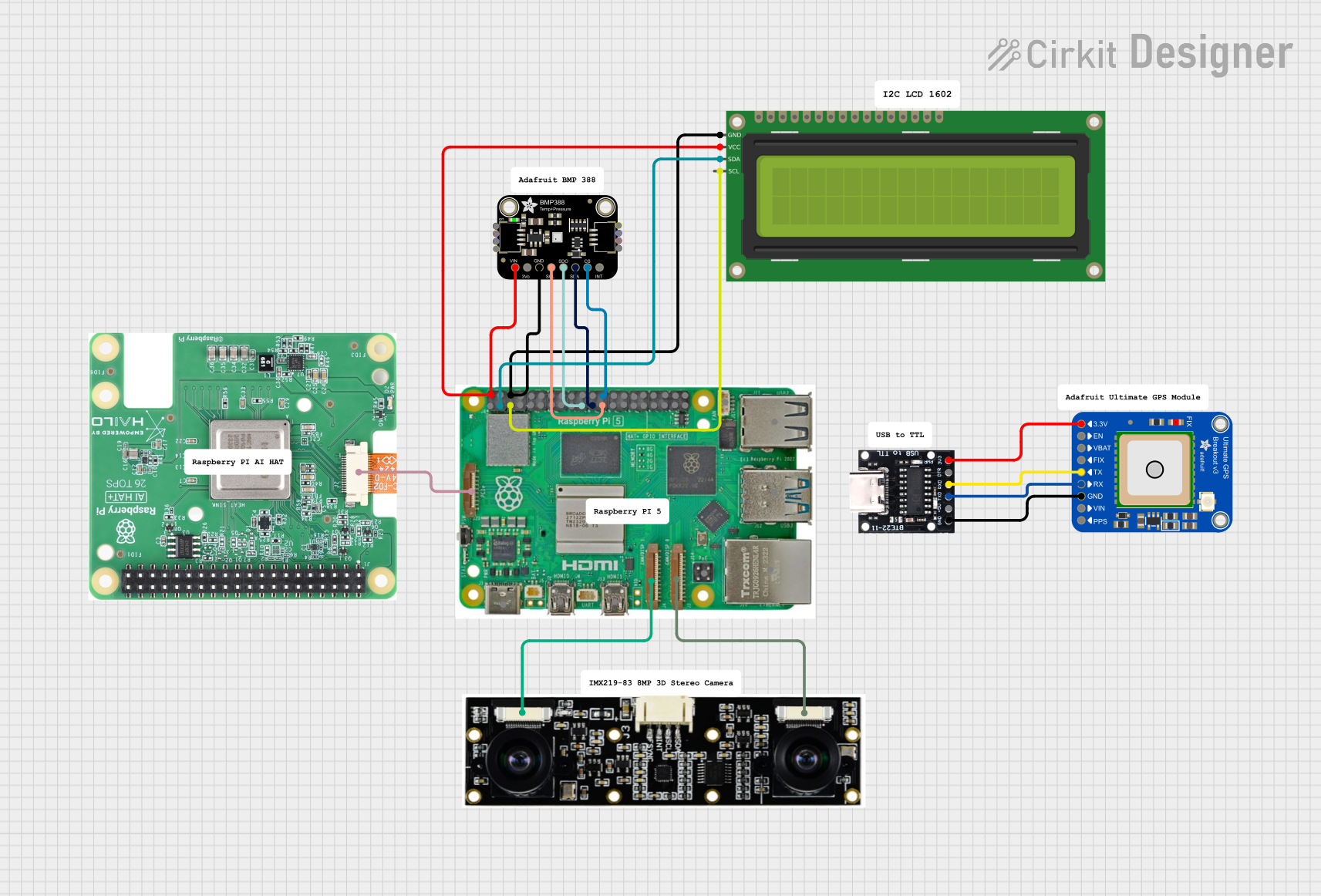

Explore Projects Built with Adafruit Raspberry Pi Perma Proto Half
Common Applications and Use Cases
- Prototyping Raspberry Pi circuits before final production
- Educational projects for learning electronics and Raspberry Pi interfacing
- DIY electronics projects that require a compact and reliable solution
- Permanent installations where a robust and long-lasting circuit is necessary
Technical Specifications
Key Technical Details
- Dimensions: 58mm x 86mm / 2.3" x 3.4"
- Weight: 20g
- Material: High-quality FR4
- Hole Pitch: Standard 0.1" (2.54mm)
- Hole Diameter: Fits 1N4148 diodes, 1/4W resistors, and 5mm LEDs perfectly
- Power Rails: Two positive and two negative rails linked to Raspberry Pi power lines
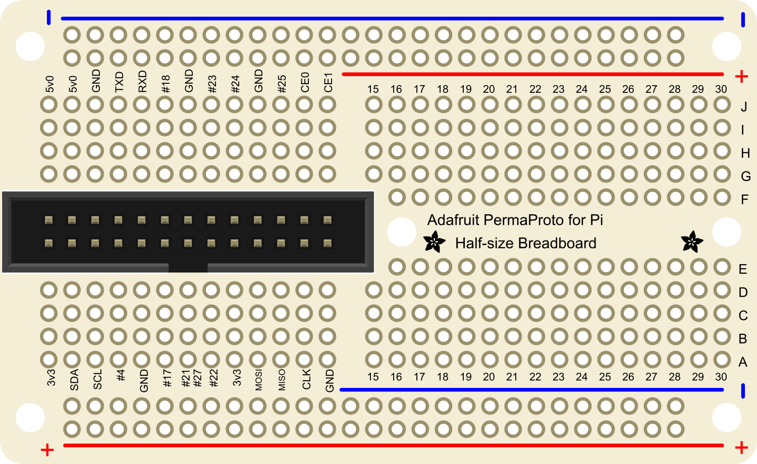
Pin Configuration and Descriptions
| Pin Number | Description | Notes |
|---|---|---|
| 1-17 | GPIO Pins | Corresponds to Raspberry Pi GPIO |
| 18-20 | Ground Rails | Connected to Raspberry Pi GND |
| 21-23 | 3.3V Power Rails | Linked to Raspberry Pi 3.3V supply |
| 24-26 | 5V Power Rails | Linked to Raspberry Pi 5V supply |
Usage Instructions
How to Use the Component in a Circuit
Planning Your Circuit:
- Begin by sketching out your circuit design on paper.
- Identify the components you will use and their connections to the Raspberry Pi GPIO pins.
Transferring the Design:
- Place your components on the Perma Proto board, aligning them with the through-holes.
- Use the power rails for distributing power to your components.
Soldering:
- Solder your components to the board, ensuring good solder joints for reliable connections.
- Trim any excess leads from components after soldering to prevent shorts.
Connecting to Raspberry Pi:
- Use jumper wires or solder connections from the Perma Proto board to the Raspberry Pi GPIO pins.
- Double-check all connections against your design before powering up.
Important Considerations and Best Practices
- Power Handling: Ensure that the power drawn from the Raspberry Pi GPIO pins does not exceed their maximum ratings.
- Short Circuits: Always check for potential short circuits before applying power to avoid damage to the Raspberry Pi and components.
- Testing: Test your circuit incrementally as you build it to isolate issues early on.
- Labeling: Consider labeling the connections on the board for easier troubleshooting and maintenance.
Troubleshooting and FAQs
Common Issues Users Might Face
- Poor Solder Joints: If a component is not working, check for cold solder joints or bridges between adjacent pins.
- Incorrect Wiring: Double-check that all components are connected as per your design and that there are no misplaced wires.
- Power Issues: Verify that the power rails are correctly linked to the Raspberry Pi power supply and that there is no overloading.
Solutions and Tips for Troubleshooting
- Reflow Solder: If a solder joint looks suspicious, reheat it and apply a small amount of fresh solder.
- Continuity Testing: Use a multimeter to check for continuity in your circuit and ensure all connections are solid.
- Power Checks: Use a multimeter to verify that the correct voltages are present at different points in the circuit.
FAQs
Q: Can I use the Perma Proto board with other microcontrollers? A: Yes, the board is not limited to the Raspberry Pi and can be used with any microcontroller that has compatible voltage levels and pin spacing.
Q: How many components can the Perma Proto board accommodate? A: The board can fit a variety of components as long as they conform to the standard 0.1" hole spacing. The exact number depends on the size of the components used.
Q: Is it possible to remove a component after soldering? A: Yes, components can be desoldered, but care must be taken to avoid lifting pads or damaging the board.
Q: Are there any power limitations for the Perma Proto board? A: The power limitations are generally dictated by the Raspberry Pi's power supply capabilities and the current ratings of the GPIO pins. Always refer to the Raspberry Pi specifications for guidance.
For further assistance or questions, please visit the Adafruit support forums or contact Adafruit customer service.