
How to Use Adafruit 2.9 inch eInk Display Breakout: Examples, Pinouts, and Specs
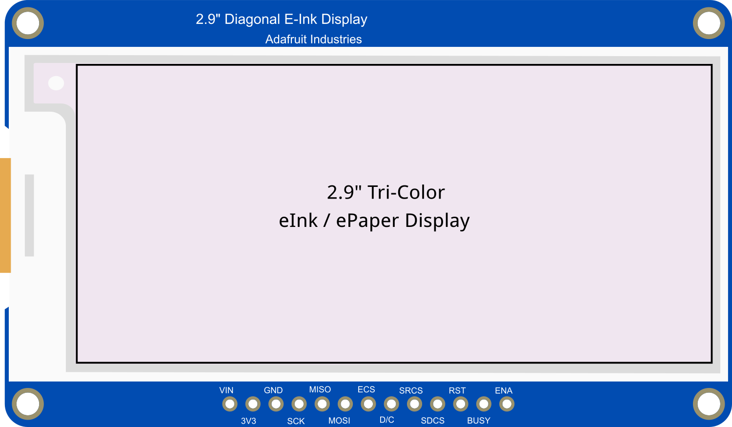
 Design with Adafruit 2.9 inch eInk Display Breakout in Cirkit Designer
Introduction
The Adafruit 2.9 inch eInk Display Breakout is a low-power display module that utilizes eInk (electronic ink) technology to deliver a paper-like reading experience. With its 2.9-inch diagonal screen, this display is perfect for applications requiring high contrast and excellent visibility, even in bright sunlight. It is ideal for displaying static images, text, or graphics with minimal power consumption, making it suitable for battery-powered devices.
Explore Projects Built with Adafruit 2.9 inch eInk Display Breakout
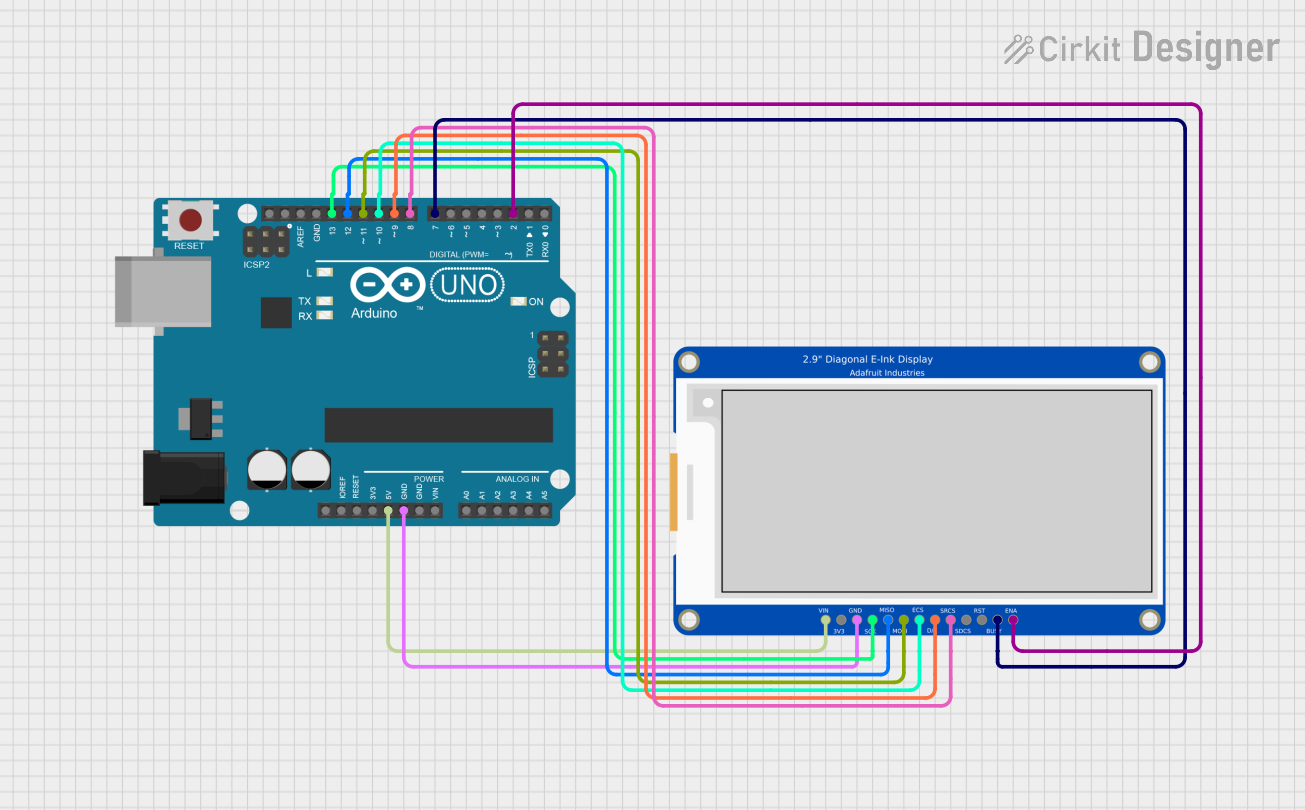 Open Project in Cirkit Designer
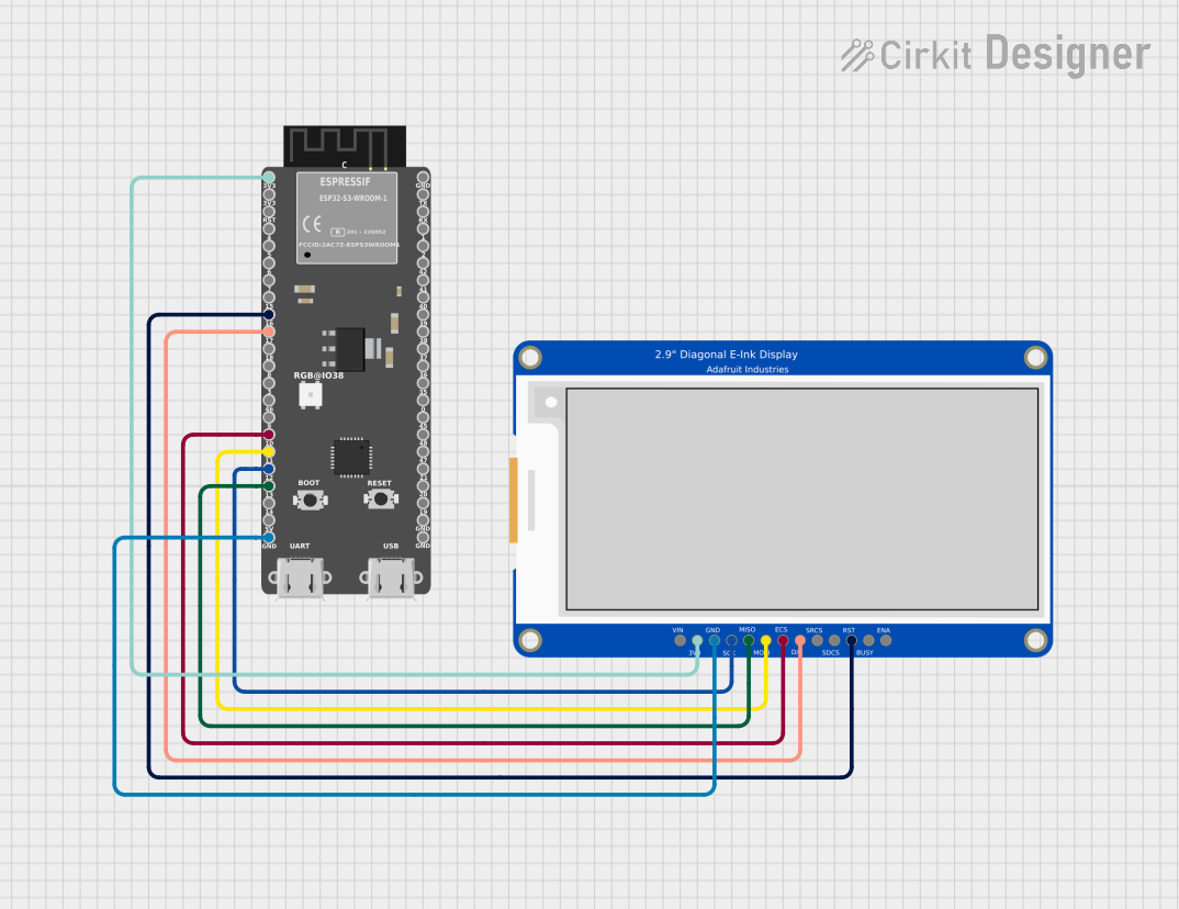 Open Project in Cirkit Designer
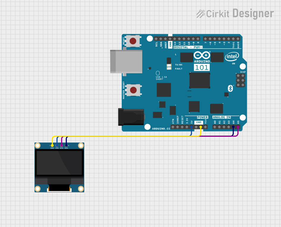 Open Project in Cirkit Designer
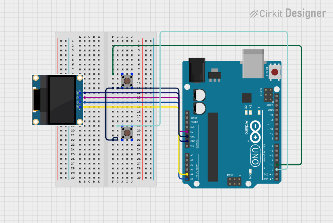 Open Project in Cirkit Designer
Explore Projects Built with Adafruit 2.9 inch eInk Display Breakout
Open Project in Cirkit DesignerOpen Project in Cirkit DesignerOpen Project in Cirkit DesignerOpen Project in Cirkit DesignerCommon Applications and Use Cases
- eBook readers
- Digital signage
- Smart home displays
- Low-power IoT devices
- Price tags and labels
- Wearable devices
Technical Specifications
Below are the key technical details of the Adafruit 2.9 inch eInk Display Breakout:
| Specification | Details |
|---|---|
| Display Technology | eInk (electronic ink) |
| Screen Size | 2.9 inches (diagonal) |
| Resolution | 296 x 128 pixels |
| Color | Black and white |
| Interface | SPI (Serial Peripheral Interface) |
| Operating Voltage | 3.3V logic |
| Power Consumption | Ultra-low power (only during updates) |
| Refresh Time | ~2 seconds |
| Dimensions | 79mm x 36mm x 4mm |
| Weight | 10g |
Pin Configuration and Descriptions
The Adafruit 2.9 inch eInk Display Breakout has the following pinout:
| Pin Name | Description |
|---|---|
| VIN | Power input (3.3V or 5V) |
| GND | Ground |
| SCK | SPI Clock |
| MOSI | SPI Master Out Slave In (data input) |
| MISO | SPI Master In Slave Out (not used in this display) |
| CS | Chip Select (active low) |
| DC | Data/Command control pin |
| RST | Reset pin (active low) |
| BUSY | Busy signal (high when the display is updating) |
Usage Instructions
How to Use the Component in a Circuit
- Power the Display: Connect the VIN pin to a 3.3V or 5V power source and the GND pin to ground.
- Connect SPI Pins: Connect the SCK, MOSI, and CS pins to the corresponding SPI pins on your microcontroller.
- Control Pins: Connect the DC, RST, and BUSY pins to GPIO pins on your microcontroller.
- Install Libraries: If using an Arduino, install the Adafruit GFX and Adafruit EPD libraries from the Arduino Library Manager.
- Write Code: Use the libraries to initialize the display, send data, and refresh the screen.
Important Considerations and Best Practices
- Avoid Frequent Refreshes: eInk displays are designed for static content. Frequent updates can reduce the lifespan of the display.
- Handle with Care: The display is fragile; avoid bending or applying pressure to the screen.
- Power Consumption: The display only consumes power during updates. Ensure your circuit design accounts for this.
- Temperature Range: Operate the display within the recommended temperature range (typically 0°C to 50°C).
Example Code for Arduino UNO
Below is an example of how to use the Adafruit 2.9 inch eInk Display Breakout with an Arduino UNO:
#include <Adafruit_GFX.h>    // Core graphics library
#include <Adafruit_EPD.h>    // eInk display library

// Define pin connections
#define EPD_CS   10  // Chip Select pin
#define EPD_DC    9  // Data/Command pin
#define SRAM_CS   -1 // Not used
#define EPD_RESET 8  // Reset pin
#define EPD_BUSY  7  // Busy pin

// Initialize the display
Adafruit_SSD1681 display(296, 128, EPD_DC, EPD_RESET, EPD_CS, SRAM_CS, EPD_BUSY);

void setup() {
  // Start serial communication for debugging
  Serial.begin(115200);
  Serial.println("Initializing eInk display...");

  // Initialize the display
  display.begin();
  display.setRotation(1); // Set display orientation
  display.setTextColor(EPD_BLACK);

  // Clear the display
  display.clearBuffer();
  display.display();

  // Display a message
  display.setCursor(10, 50); // Set text position
  display.setTextSize(2);    // Set text size
  display.print("Hello, eInk!");
  display.display();         // Update the display
}

void loop() {
  // Nothing to do here
}
Troubleshooting and FAQs
Common Issues and Solutions
Display Not Turning On:
- Ensure the VIN and GND pins are properly connected to the power source.
- Verify that the SPI connections (SCK, MOSI, CS) are correct.
No Output on the Screen:
- Check the DC, RST, and BUSY pin connections.
- Ensure the Adafruit GFX and Adafruit EPD libraries are installed and up to date.
Screen Refresh is Slow:
- eInk displays have a natural refresh time of ~2 seconds. This is normal behavior.
Partial Updates Not Working:
- Some eInk displays do not support partial updates. Refer to the product datasheet for details.
FAQs
Q: Can I use this display with a 5V microcontroller?
A: Yes, the breakout board includes level-shifting circuitry, allowing it to work with both 3.3V and 5V logic.
Q: How long does the image remain on the screen without power?
A: The image will remain indefinitely until the display is refreshed, as eInk technology is bistable.
Q: Can I display grayscale images?
A: No, this display supports only black and white.
Q: Is the display sunlight-readable?
A: Yes, eInk displays are highly visible in direct sunlight.
Q: What is the lifespan of the display?
A: The display is rated for thousands of refresh cycles. Avoid excessive updates to maximize lifespan.