How to Use Adafruit 8x16 LED Matrix FeatherWing - Yellow: Examples, Pinouts, and Specs
Introduction
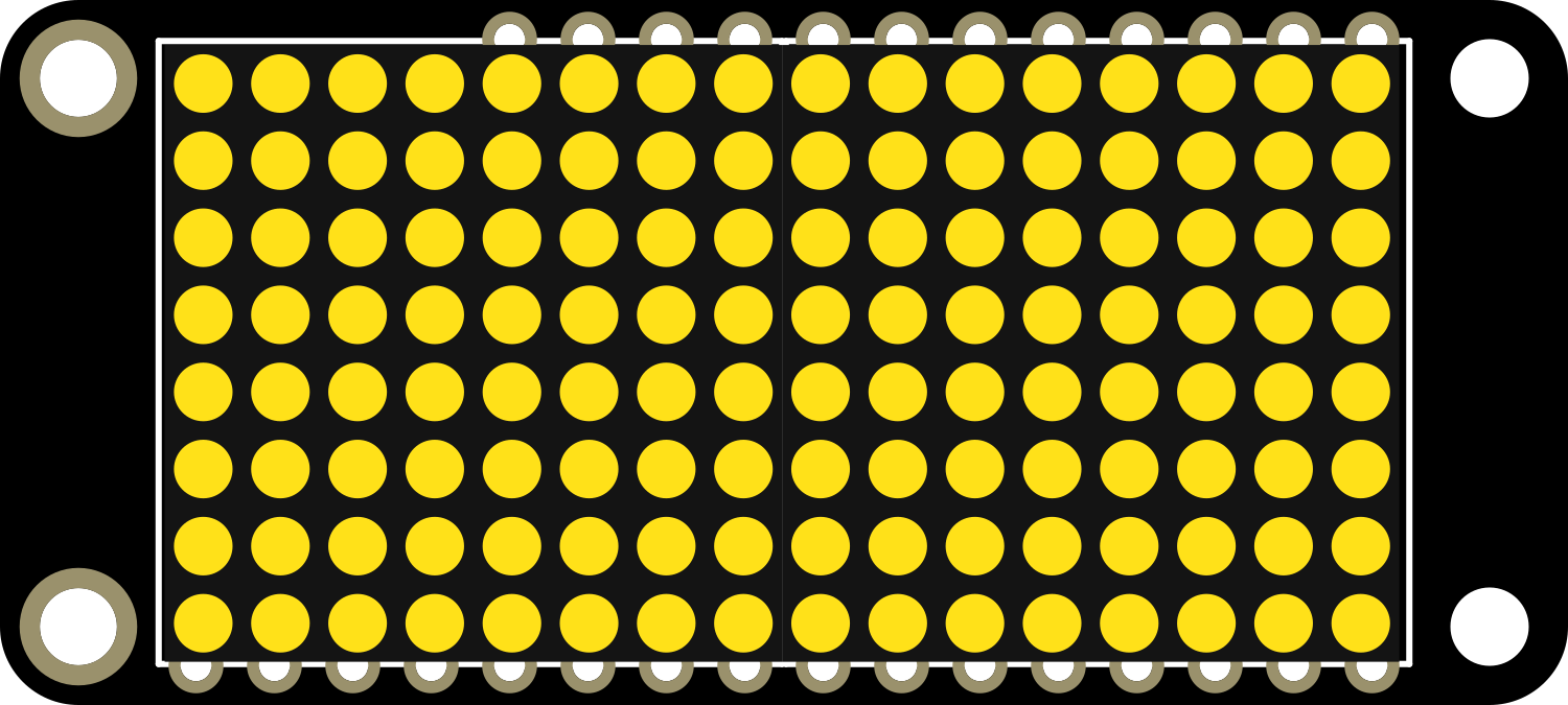
The Adafruit 8x16 LED Matrix FeatherWing - Yellow is a versatile and compact LED matrix display designed for integration with the Adafruit Feather series of development boards. This expansion board features a grid of 8x16 individually addressable yellow LEDs, allowing for a wide range of visual output possibilities. It is commonly used for creating scrolling text displays, simple animations, and other visual indicators in portable projects.
Explore Projects Built with Adafruit 8x16 LED Matrix FeatherWing - Yellow

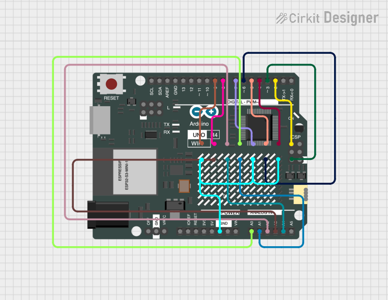

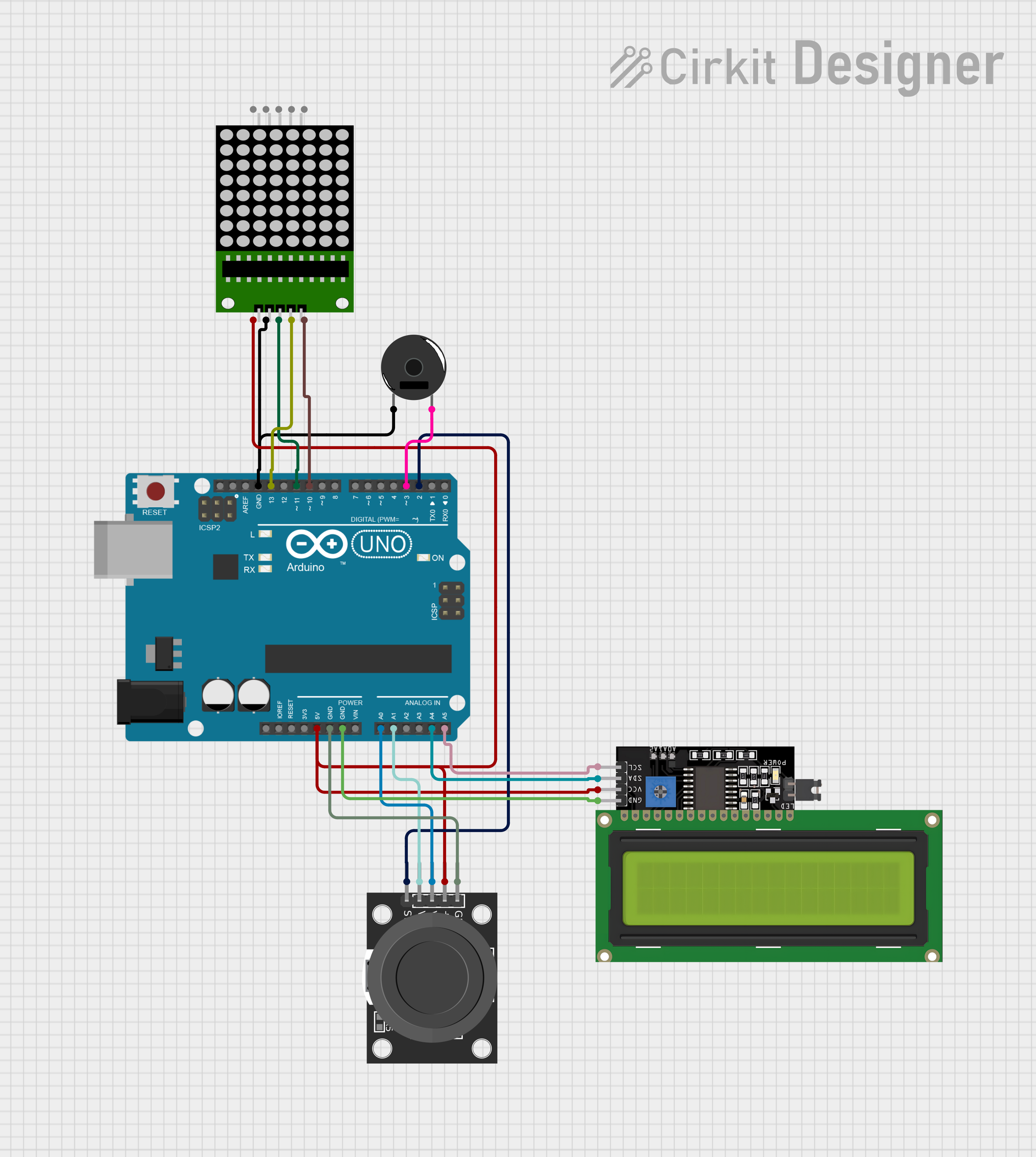
Explore Projects Built with Adafruit 8x16 LED Matrix FeatherWing - Yellow
Common Applications and Use Cases
- Wearable electronics
- Portable message displays
- Data visualization for sensors
- User interfaces for projects
- Educational tools for learning programming and electronics
Technical Specifications
Key Technical Details
- LED Color: Yellow
- Matrix Size: 8x16 LEDs
- Communication: I2C interface
- Operating Voltage: 3.3V to 5V (Feather compatible)
- Dimensions: 51mm x 23mm x 4.6mm / 2.0" x 0.9" x 0.18"
- Weight: 4.8 grams
Pin Configuration and Descriptions
| Pin | Description |
|---|---|
| GND | Ground connection |
| 3V | 3.3V power supply |
| SDA | I2C data line |
| SCL | I2C clock line |
| ADDR | I2C address selection (optional) |
| RST | Reset pin (optional) |
Usage Instructions
How to Use the Component in a Circuit
- Power Connection: Connect the 3V pin to the 3.3V output on your Feather board and GND to ground.
- I2C Connection: Connect SDA and SCL pins to the corresponding I2C pins on your Feather board.
- Address Selection (Optional): If using multiple LED matrices, you can set different I2C addresses by connecting the ADDR pin to ground or 3V.
- Reset (Optional): The RST pin can be connected to a digital pin on your Feather board to allow software reset of the LED matrix.
Important Considerations and Best Practices
- Ensure that your Feather board can supply enough current for the LED matrix.
- When using multiple matrices, verify that the total current does not exceed the power supply capabilities.
- Avoid looking directly at the LEDs for extended periods to prevent eye strain or damage.
Example Code for Arduino UNO
#include <Wire.h>
#include <Adafruit_GFX.h>
#include <Adafruit_LEDBackpack.h>

Adafruit_8x16matrix matrix = Adafruit_8x16matrix();

void setup() {
  matrix.begin(0x70); // Initialize the matrix with its I2C address
  matrix.setBrightness(10); // Set the brightness to a medium level
  matrix.clear(); // Clear the matrix display
}

void loop() {
  matrix.clear(); // Clear the matrix display
  matrix.setCursor(0, 0); // Set cursor at top-left corner
  matrix.print(F("Hello")); // Print a message to the matrix
  matrix.writeDisplay(); // Update the display with the new data
  delay(2000); // Wait for 2 seconds
  matrix.scrollLeft(); // Scroll the message to the left
  matrix.writeDisplay(); // Update the display with the new data
  delay(200); // Wait for 200 milliseconds
}
Troubleshooting and FAQs
Common Issues Users Might Face
- LEDs Not Lighting Up: Ensure that the power and I2C connections are secure and correct. Check that the Feather board is powered on.
- Garbled Display Output: Verify that the I2C address is correctly set and that there are no conflicts with other I2C devices.
- Dim LEDs: Increase the brightness setting in your code or check the power supply for adequate current.
Solutions and Tips for Troubleshooting
- Double-check wiring connections and solder joints for any loose connections or shorts.
- Use the
i2cdetectutility or similar tools to confirm the I2C address of the LED matrix. - Ensure that the library and board definitions are up to date in your development environment.
FAQs
Q: Can I use this LED matrix with boards other than Feather? A: Yes, as long as the board supports I2C communication and operates within the voltage range.
Q: How do I chain multiple LED matrices together? A: You can chain multiple matrices by connecting their I2C lines in parallel and setting unique I2C addresses for each matrix.
Q: Can I display images on the LED matrix? A: Yes, you can display bitmap images, but they need to be formatted for the 8x16 resolution and converted into the appropriate format for the Adafruit GFX library.
Q: Is it possible to use this LED matrix with a 5V system? A: The matrix is designed to be 5V tolerant on the I2C lines, but it is recommended to use a level shifter for reliable operation.