How to Use REX C-100: Examples, Pinouts, and Specs
Introduction
The REX C-100, manufactured by RKC Instruments Inc. (Part ID: FK02-M*AN), is a compact and versatile electronic component designed for signal processing and control applications. It is widely used in industrial and hobbyist projects due to its flexibility, reliability, and ease of integration into various circuit designs. The REX C-100 supports a range of input and output options, making it suitable for temperature control, automation systems, and other precision control applications.
Explore Projects Built with REX C-100
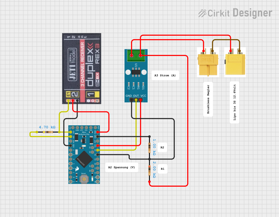


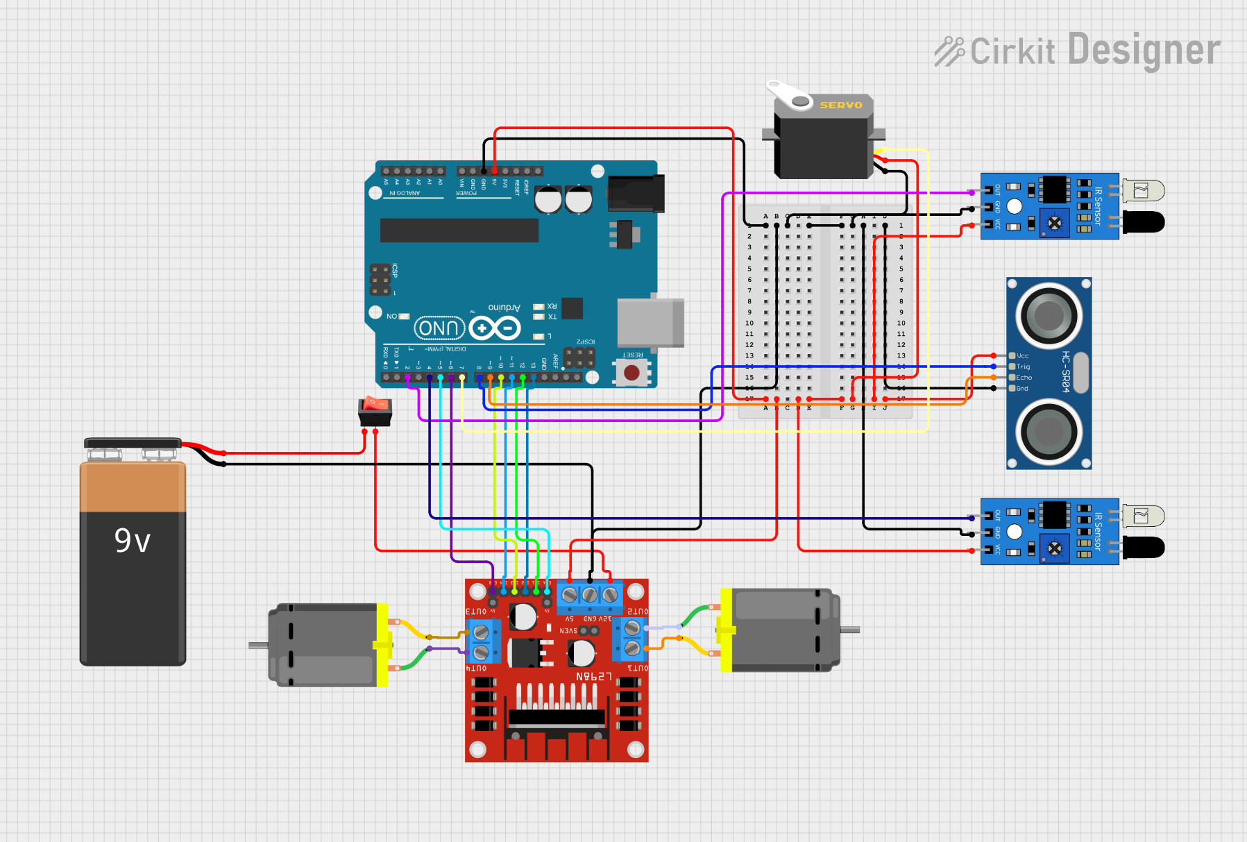
Explore Projects Built with REX C-100
Common Applications
- Temperature control in industrial systems
- Automation and process control
- Signal conditioning and processing
- Integration into microcontroller-based systems (e.g., Arduino)
- Hobbyist and DIY electronics projects
Technical Specifications
Key Technical Details
| Parameter | Specification |
|---|---|
| Manufacturer | RKC Instruments Inc. |
| Part ID | FK02-M*AN |
| Input Voltage Range | 85–264 VAC |
| Output Type | Relay or SSR (Solid State Relay) |
| Input Signal Types | Thermocouple (K, J, etc.), RTD (Pt100) |
| Control Method | PID (Proportional-Integral-Derivative) |
| Display Type | LED (4-digit, dual display) |
| Operating Temperature | -10°C to 55°C |
| Dimensions | 48mm x 48mm x 110mm |
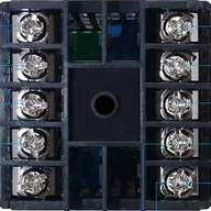
Pin Configuration and Descriptions
The REX C-100 has a terminal block for wiring connections. Below is the pin configuration:
| Pin Number | Label | Description |
|---|---|---|
| 1 | Input+ | Positive terminal for input signal (e.g., thermocouple) |
| 2 | Input- | Negative terminal for input signal |
| 3 | Output+ | Positive terminal for output (Relay/SSR control) |
| 4 | Output- | Negative terminal for output |
| 5 | Power (L) | Live terminal for AC power input |
| 6 | Power (N) | Neutral terminal for AC power input |
| 7 | Alarm Output+ | Positive terminal for alarm signal |
| 8 | Alarm Output- | Negative terminal for alarm signal |
Usage Instructions
How to Use the REX C-100 in a Circuit
- Power Connection: Connect the AC power supply to the
Power (L)andPower (N)terminals. Ensure the voltage is within the specified range (85–264 VAC). - Input Signal: Connect the input device (e.g., thermocouple or RTD) to the
Input+andInput-terminals. Ensure the input type matches the configuration of the REX C-100. - Output Connection: Connect the output terminals (
Output+andOutput-) to the load or control device (e.g., heater, motor, or SSR). - Alarm Wiring (Optional): If using the alarm feature, connect the alarm device to the
Alarm Output+andAlarm Output-terminals. - Configuration: Use the front panel buttons to configure the input type, control method (PID), and setpoint values. Refer to the user manual for detailed programming instructions.
Important Considerations and Best Practices
- Input Type Configuration: Ensure the input type (e.g., thermocouple type K or RTD) is correctly set in the device settings to avoid inaccurate readings.
- Load Compatibility: Verify that the connected load (e.g., heater or motor) is compatible with the output type (Relay or SSR).
- Grounding: Properly ground the device to prevent electrical noise and ensure safe operation.
- Ventilation: Install the REX C-100 in a well-ventilated area to prevent overheating.
- Testing: Before connecting to a live system, test the configuration with a dummy load to ensure proper operation.
Example: Connecting to an Arduino UNO
The REX C-100 can be used with an Arduino UNO for advanced control. Below is an example of reading the temperature from the REX C-100 and controlling a relay:
// Example: Reading temperature from REX C-100 and controlling a relay
// Ensure proper wiring between Arduino and REX C-100
// Pin connections:
// - REX C-100 Output+ to Arduino digital pin 2
// - REX C-100 Output- to Arduino GND
// - Relay control pin to Arduino digital pin 8

const int rexInputPin = 2;  // Digital pin connected to REX C-100 Output+
const int relayPin = 8;     // Digital pin connected to relay control

void setup() {
  pinMode(rexInputPin, INPUT);  // Set REX C-100 input pin as input
  pinMode(relayPin, OUTPUT);    // Set relay pin as output
  Serial.begin(9600);           // Initialize serial communication
}

void loop() {
  int rexSignal = digitalRead(rexInputPin);  // Read signal from REX C-100
  Serial.print("REX C-100 Signal: ");
  Serial.println(rexSignal);

  if (rexSignal == HIGH) {
    digitalWrite(relayPin, HIGH);  // Turn on relay if signal is HIGH
    Serial.println("Relay ON");
  } else {
    digitalWrite(relayPin, LOW);   // Turn off relay if signal is LOW
    Serial.println("Relay OFF");
  }

  delay(1000);  // Wait for 1 second
}
Troubleshooting and FAQs
Common Issues and Solutions
| Issue | Possible Cause | Solution |
|---|---|---|
| No display or power | Incorrect power connection | Verify AC power wiring and voltage range. |
| Inaccurate temperature readings | Incorrect input type configuration | Check and set the correct input type. |
| Output not activating | Load not connected or incompatible | Verify load connection and compatibility. |
| Alarm signal not working | Alarm not configured in settings | Configure alarm parameters in the menu. |
| Overheating of the device | Poor ventilation or high ambient temp | Ensure proper ventilation and cooling. |
FAQs
Can the REX C-100 be used with DC power?
- No, the REX C-100 is designed for AC power input (85–264 VAC).
What input types are supported?
- The REX C-100 supports thermocouples (e.g., K, J) and RTDs (e.g., Pt100).
How do I reset the device to factory settings?
- Refer to the user manual for the reset procedure, typically accessible via the front panel menu.
Can I use the REX C-100 for non-temperature control applications?
- Yes, the REX C-100 can be used for general-purpose signal processing and control tasks.
By following this documentation, users can effectively integrate the REX C-100 into their projects and troubleshoot common issues.