Cirkit Designer Logo
Cirkit Designer
Your all-in-one circuit design IDE
Home / 
Component Documentation

How to Use HuskyLens 2 Power Board: Examples, Pinouts, and Specs

Image of HuskyLens 2 Power Board
Cirkit Designer LogoDesign with HuskyLens 2 Power Board in Cirkit Designer

Introduction

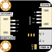
The HuskyLens 2 Power Board by DFRobot is a power management module specifically designed for the HuskyLens 2 AI camera module. It ensures a stable and reliable power supply while offering convenient connectivity for various peripherals. This board is ideal for projects requiring consistent power delivery to the HuskyLens 2 and its associated components, such as microcontrollers, sensors, and actuators.

Explore Projects Built with HuskyLens 2 Power Board

Use Cirkit Designer to design, explore, and prototype these projects online. Some projects support real-time simulation. Click "Open Project" to start designing instantly!
Arduino Uno R3 Controlled Pan-Tilt Security Camera with Night Vision
Image of MOTION CAMERA: A project utilizing HuskyLens 2 Power Board in a practical application
This circuit features an Arduino Uno R3 microcontroller connected to a Huskylens (an AI camera module), an IR LED Night Vision Ring, and a Tilt Pan module. The Huskylens is interfaced with the Arduino via I2C communication using the SDA and SCL lines, while the Tilt Pan module is controlled by the Arduino through digital pins 10 and 11 for signal and output control. The IR LED ring and Tilt Pan are powered directly from the Arduino's 5V output, and all components share a common ground.
Cirkit Designer LogoOpen Project in Cirkit Designer
Battery-Powered FPV Drone with Telemetry and Dual Motor Control
Image of Krul': A project utilizing HuskyLens 2 Power Board in a practical application
This circuit appears to be a power distribution and control system for a vehicle with two motorized wheels, possibly a drone or a robot. It includes a lipo battery connected to a Power Distribution Board (PDB) that distributes power to two Electronic Speed Controllers (ESCs) which in turn control the speed and direction of the motors. The system also integrates a flight controller (H743-SLIM V3) for managing various peripherals including GPS, FPV camera system, and a telemetry link (ExpressLRS).
Cirkit Designer LogoOpen Project in Cirkit Designer
Arduino UNO Controlled RGB LED and Servo System with Capacitive Sensing and HuskyLens Vision
Image of orca: A project utilizing HuskyLens 2 Power Board in a practical application
This circuit features an Arduino UNO microcontroller connected to a Huskylens for image processing, a capacitive sensor for touch input, and a multi-channel PWM servo shield controlling several servos. The Arduino is powered by 5V and shares a common ground with the Huskylens and capacitive sensor, which also interface with the Arduino's analog and I2C pins, respectively. The servos are powered by a battery through a DC-DC step-down converter, and their control signals are managed by the PWM servo shield, which is also connected to the Arduino for I2C communication.
Cirkit Designer LogoOpen Project in Cirkit Designer
Arduino Mega 2560 Battery-Powered Robotic System with Multiple Sensors and Motor Control
Image of Bullshit: A project utilizing HuskyLens 2 Power Board in a practical application
This circuit is a complex control system powered by multiple 18650 Li-ion batteries, featuring an Arduino Mega 2560 microcontroller that interfaces with various sensors, servos, and motor drivers. The system includes multiple LEDs for status indication, a HuskyLens for visual processing, and VL53L0X sensors for distance measurement. The Arduino controls the motors and sensors, enabling advanced automation and robotics applications.
Cirkit Designer LogoOpen Project in Cirkit Designer

Explore Projects Built with HuskyLens 2 Power Board

Use Cirkit Designer to design, explore, and prototype these projects online. Some projects support real-time simulation. Click "Open Project" to start designing instantly!
Image of MOTION CAMERA: A project utilizing HuskyLens 2 Power Board in a practical application
Arduino Uno R3 Controlled Pan-Tilt Security Camera with Night Vision
This circuit features an Arduino Uno R3 microcontroller connected to a Huskylens (an AI camera module), an IR LED Night Vision Ring, and a Tilt Pan module. The Huskylens is interfaced with the Arduino via I2C communication using the SDA and SCL lines, while the Tilt Pan module is controlled by the Arduino through digital pins 10 and 11 for signal and output control. The IR LED ring and Tilt Pan are powered directly from the Arduino's 5V output, and all components share a common ground.
Cirkit Designer LogoOpen Project in Cirkit Designer
Image of Krul': A project utilizing HuskyLens 2 Power Board in a practical application
Battery-Powered FPV Drone with Telemetry and Dual Motor Control
This circuit appears to be a power distribution and control system for a vehicle with two motorized wheels, possibly a drone or a robot. It includes a lipo battery connected to a Power Distribution Board (PDB) that distributes power to two Electronic Speed Controllers (ESCs) which in turn control the speed and direction of the motors. The system also integrates a flight controller (H743-SLIM V3) for managing various peripherals including GPS, FPV camera system, and a telemetry link (ExpressLRS).
Cirkit Designer LogoOpen Project in Cirkit Designer
Image of orca: A project utilizing HuskyLens 2 Power Board in a practical application
Arduino UNO Controlled RGB LED and Servo System with Capacitive Sensing and HuskyLens Vision
This circuit features an Arduino UNO microcontroller connected to a Huskylens for image processing, a capacitive sensor for touch input, and a multi-channel PWM servo shield controlling several servos. The Arduino is powered by 5V and shares a common ground with the Huskylens and capacitive sensor, which also interface with the Arduino's analog and I2C pins, respectively. The servos are powered by a battery through a DC-DC step-down converter, and their control signals are managed by the PWM servo shield, which is also connected to the Arduino for I2C communication.
Cirkit Designer LogoOpen Project in Cirkit Designer
Image of Bullshit: A project utilizing HuskyLens 2 Power Board in a practical application
Arduino Mega 2560 Battery-Powered Robotic System with Multiple Sensors and Motor Control
This circuit is a complex control system powered by multiple 18650 Li-ion batteries, featuring an Arduino Mega 2560 microcontroller that interfaces with various sensors, servos, and motor drivers. The system includes multiple LEDs for status indication, a HuskyLens for visual processing, and VL53L0X sensors for distance measurement. The Arduino controls the motors and sensors, enabling advanced automation and robotics applications.
Cirkit Designer LogoOpen Project in Cirkit Designer

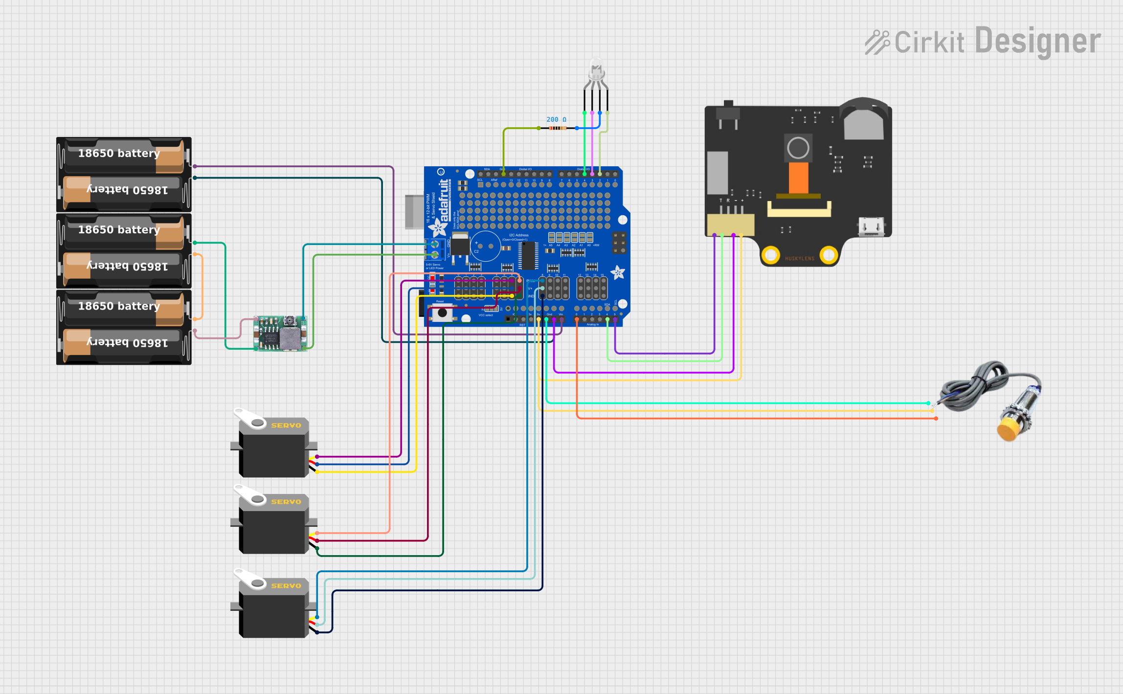
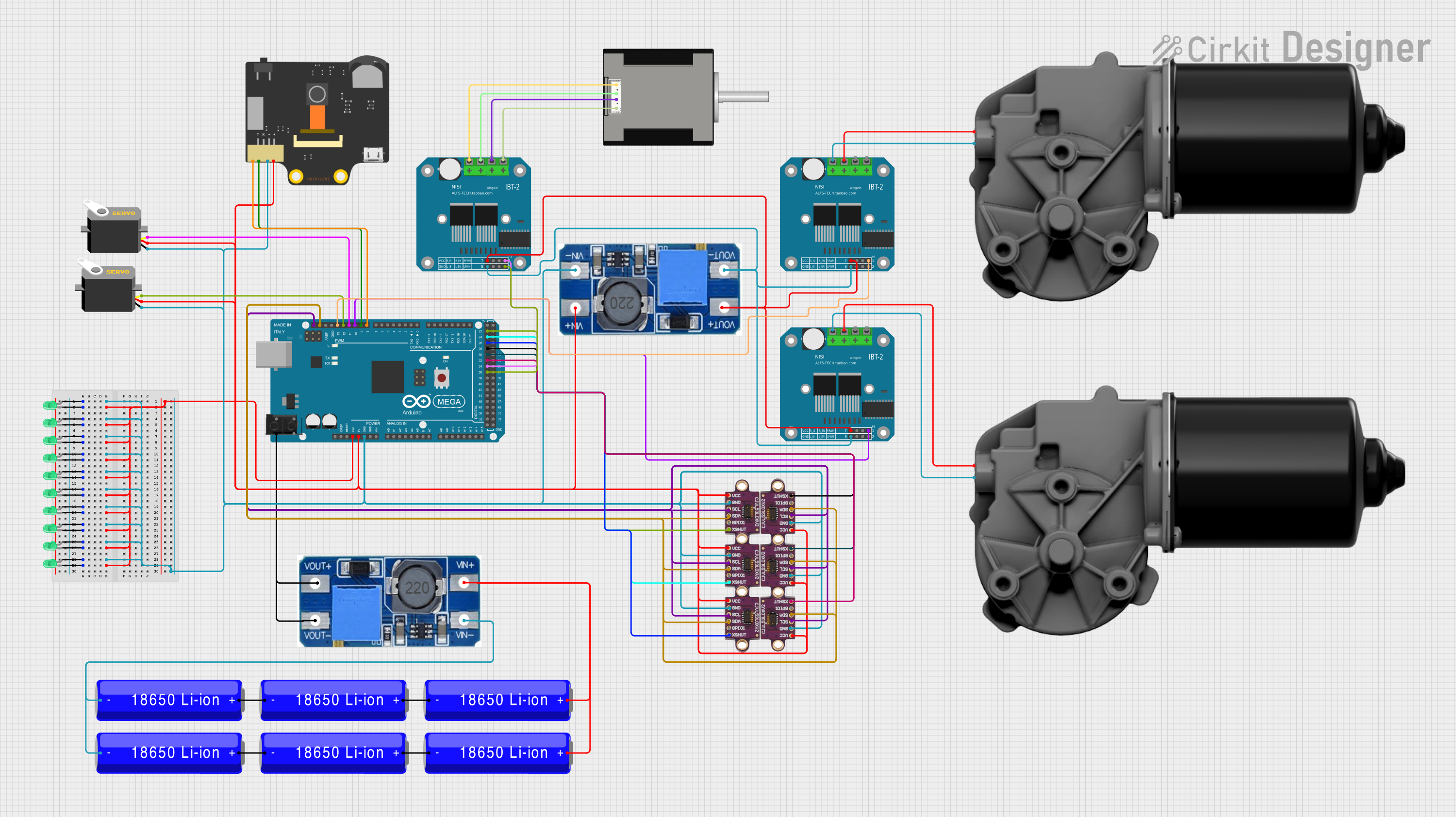
Common Applications and Use Cases

  • Powering the HuskyLens 2 AI camera module in robotics and AI projects.
  • Providing stable power for microcontroller-based systems (e.g., Arduino, Raspberry Pi).
  • Simplifying connections in IoT and machine vision applications.
  • Supporting portable or battery-powered setups for AI-based projects.

Technical Specifications

The HuskyLens 2 Power Board is designed to meet the power and connectivity needs of the HuskyLens 2 module and its peripherals. Below are the key technical details:

Key Specifications

Parameter Value
Input Voltage Range 5V DC (via USB-C)
Output Voltage 3.3V / 5V DC (selectable)
Maximum Output Current 2A
Power Connector Type USB-C
Peripheral Connections 4-pin Grove interface
Dimensions 40mm x 30mm x 10mm
Weight 10g

Pin Configuration and Descriptions

The HuskyLens 2 Power Board features a simple pinout for easy integration with the HuskyLens 2 module and other peripherals.

Grove Interface Pinout

Pin Name Description
VCC Power output (3.3V or 5V, selectable)
GND Ground
SDA I2C Data Line
SCL I2C Clock Line

USB-C Port

Pin Name Description
VBUS 5V Power Input
GND Ground

Usage Instructions

The HuskyLens 2 Power Board is straightforward to use and integrates seamlessly with the HuskyLens 2 AI camera module. Follow the steps below to set up and use the board:

Step 1: Powering the Board

  1. Connect a 5V DC power source to the USB-C port of the power board.
  2. Ensure the power source can supply at least 2A to avoid power instability.

Step 2: Connecting the HuskyLens 2 Module

  1. Use the 4-pin Grove cable to connect the HuskyLens 2 module to the Grove interface on the power board.
  2. Ensure the VCC and GND pins are correctly aligned to avoid damage.

Step 3: Selecting Output Voltage

  1. Use the onboard voltage selection jumper to choose between 3.3V and 5V output.
  2. Set the jumper to match the voltage requirements of your connected peripherals.

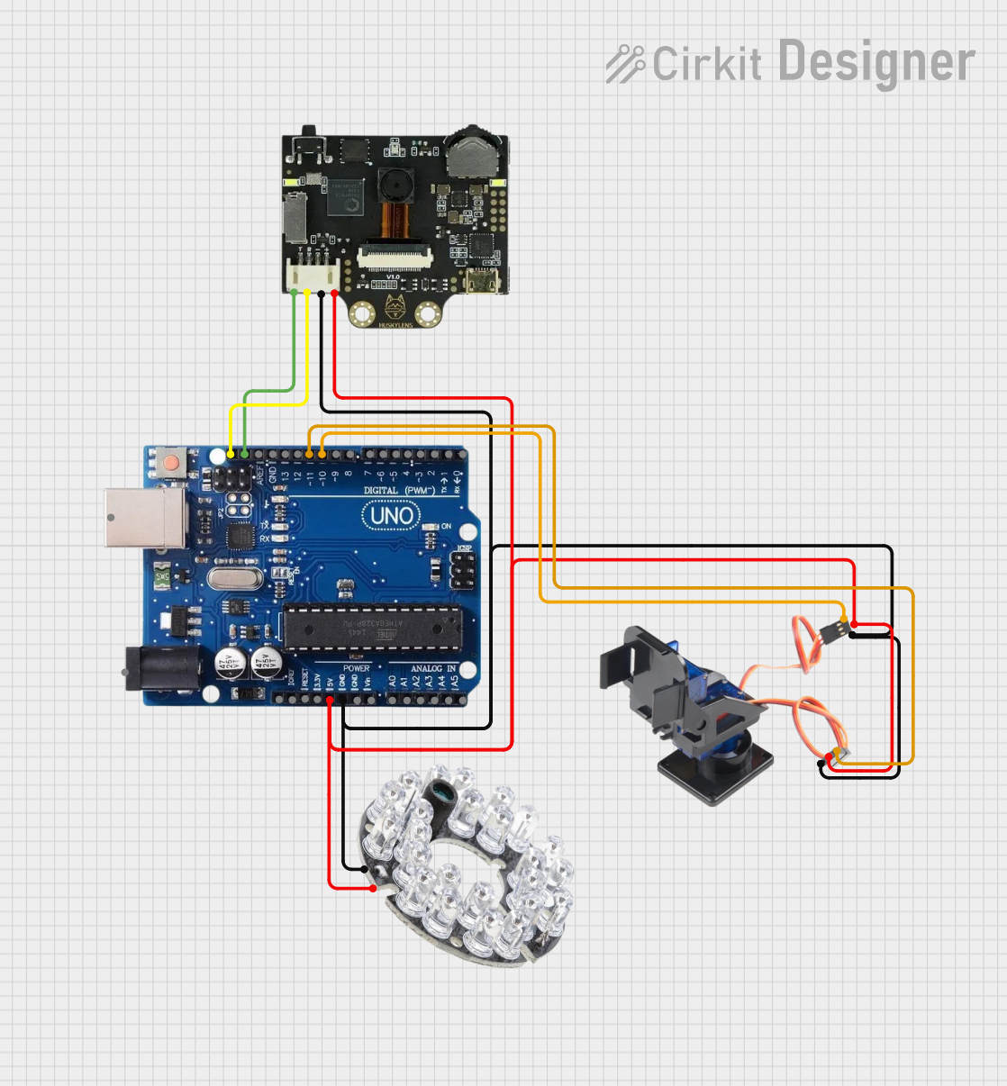
Step 4: Integrating with an Arduino UNO

The HuskyLens 2 Power Board can be connected to an Arduino UNO for AI-based projects. Below is an example code snippet to interface the HuskyLens 2 module with the Arduino UNO:

#include <Wire.h>

// Define the I2C address of the HuskyLens 2 module
#define HUSKYLENS_I2C_ADDRESS 0x32

void setup() {
  Wire.begin(); // Initialize I2C communication
  Serial.begin(9600); // Start serial communication for debugging

  // Check if the HuskyLens 2 module is connected
  Wire.beginTransmission(HUSKYLENS_I2C_ADDRESS);
  if (Wire.endTransmission() == 0) {
    Serial.println("HuskyLens 2 module detected!");
  } else {
    Serial.println("Error: HuskyLens 2 module not detected.");
  }
}

void loop() {
  // Example: Request data from the HuskyLens 2 module
  Wire.requestFrom(HUSKYLENS_I2C_ADDRESS, 6); // Request 6 bytes of data
  while (Wire.available()) {
    char c = Wire.read(); // Read each byte
    Serial.print(c); // Print the received data
  }
  delay(1000); // Wait for 1 second before the next request
}

Best Practices

  • Always verify the voltage requirements of your peripherals before connecting them to the power board.
  • Use a high-quality USB-C cable and power adapter to ensure stable power delivery.
  • Avoid short circuits by carefully aligning the Grove connector pins.

Troubleshooting and FAQs

Common Issues and Solutions

  1. HuskyLens 2 module not powering on:

    • Ensure the USB-C power source is providing at least 5V and 2A.
    • Check the Grove cable connection for proper alignment.
  2. Peripheral devices not receiving power:

    • Verify the voltage selection jumper is set to the correct output voltage (3.3V or 5V).
    • Inspect the Grove cable for any damage or loose connections.
  3. I2C communication errors:

    • Confirm the SDA and SCL lines are correctly connected.
    • Check for address conflicts if multiple I2C devices are connected.

FAQs

Q: Can I use a battery pack to power the HuskyLens 2 Power Board?
A: Yes, as long as the battery pack provides a stable 5V output via USB-C and can supply at least 2A.

Q: Is the power board compatible with other Grove modules?
A: Yes, the Grove interface on the power board can be used with other Grove-compatible modules, provided they operate at 3.3V or 5V.

Q: How do I know if the power board is working correctly?
A: The onboard LED indicator will light up when the board is powered and functioning properly.

By following this documentation, you can effectively use the HuskyLens 2 Power Board in your projects and troubleshoot any issues that may arise.