Cirkit Designer
Your all-in-one circuit design IDE
Home /
Component Documentation
How to Use MAX7219 display 7 segment 4 digit: Examples, Pinouts, and Specs
Introduction
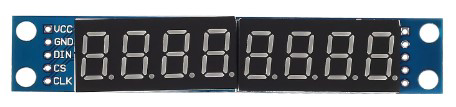
The MAX7219 is an integrated serial input/output common-cathode display driver designed to interface microprocessors with 7-segment numeric LED displays of up to 8 digits, bar-graph displays, or 64 individual LEDs. It includes a BCD code-B decoder, multiplex scan circuitry, segment and digit drivers, and an 8x8 static RAM for storing each digit. This documentation focuses on using the MAX7219 to drive a 4-digit 7-segment display.
Explore Projects Built with MAX7219 display 7 segment 4 digit
Teensy 4.0 and MAX7219-Based 7-Segment Display Counter

This circuit uses a Teensy 4.0 microcontroller to control a MAX7219 LED driver, which in turn drives three 7-segment displays. The microcontroller runs code to display numbers from 0 to 999 on the 7-segment displays, with the SN74AHCT125N buffer providing signal integrity and the necessary capacitors and resistors ensuring stable operation.
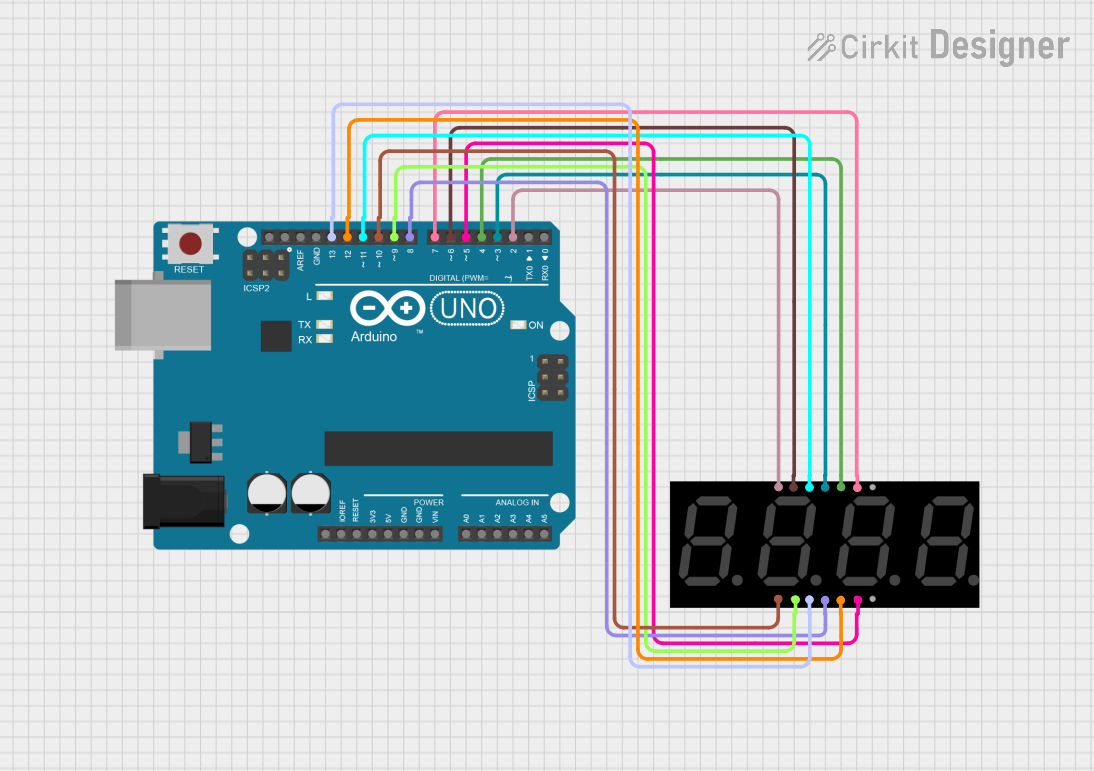
Arduino UNO 4-Digit 7-Segment Display Counter
This circuit uses an Arduino UNO to control a 4-digit 7-segment display. The Arduino is programmed to sequentially display the numbers 1, 2, 3, and 4 on the display by driving the appropriate segments and digits.
Arduino UNO 4-Digit Seven Segment Display Counter
This circuit uses an Arduino UNO to control a 4-digit seven-segment display. The Arduino runs a program that counts up in deci-seconds and displays the count on the seven-segment display using the SevSeg library.
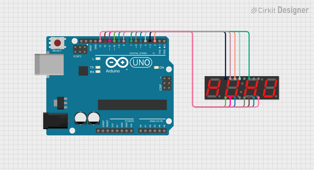
Arduino UNO Controlled LED and 7-Segment Display Circuit
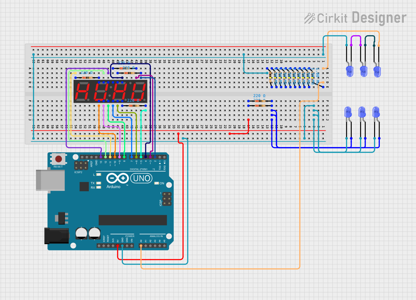
This circuit features an Arduino UNO controlling multiple blue LEDs and a 4-digit 7-segment display. The LEDs are configured with current-limiting resistors, and the display is interfaced with the Arduino for potential numeric or character output. The provided code for the Arduino is a template without specific functionality.
Explore Projects Built with MAX7219 display 7 segment 4 digit
Teensy 4.0 and MAX7219-Based 7-Segment Display Counter
This circuit uses a Teensy 4.0 microcontroller to control a MAX7219 LED driver, which in turn drives three 7-segment displays. The microcontroller runs code to display numbers from 0 to 999 on the 7-segment displays, with the SN74AHCT125N buffer providing signal integrity and the necessary capacitors and resistors ensuring stable operation.
Arduino UNO 4-Digit 7-Segment Display Counter
This circuit uses an Arduino UNO to control a 4-digit 7-segment display. The Arduino is programmed to sequentially display the numbers 1, 2, 3, and 4 on the display by driving the appropriate segments and digits.
Arduino UNO 4-Digit Seven Segment Display Counter
This circuit uses an Arduino UNO to control a 4-digit seven-segment display. The Arduino runs a program that counts up in deci-seconds and displays the count on the seven-segment display using the SevSeg library.
Arduino UNO Controlled LED and 7-Segment Display Circuit
This circuit features an Arduino UNO controlling multiple blue LEDs and a 4-digit 7-segment display. The LEDs are configured with current-limiting resistors, and the display is interfaced with the Arduino for potential numeric or character output. The provided code for the Arduino is a template without specific functionality.
Common Applications and Use Cases
- Digital clocks
- Electronic meters
- Instrumentation readouts
- Scoreboards
- LED matrix displays
Technical Specifications
Key Technical Details
| Parameter | Value |
|---|---|
| Operating Voltage | 4.0V to 5.5V |
| Supply Current | 330mA (typical) |
| Power Dissipation | 600mW |
| Operating Temperature | -40°C to +85°C |
| Display Type | 7-segment, 4-digit |
| Interface | Serial (SPI compatible) |
Pin Configuration and Descriptions
| Pin No. | Pin Name | Description |
|---|---|---|
| 1 | DIN | Serial Data Input |
| 2 | LOAD | Load Data Input (CS) |
| 3 | CLK | Serial Clock Input |
| 4 | DOUT | Serial Data Output |
| 5 | GND | Ground |
| 6 | VCC | Power Supply |
| 7-14 | SEG A-G, DP | Segment Outputs (A-G, Decimal Point) |
| 15-22 | DIG 0-7 | Digit Outputs (0-7) |
Usage Instructions
How to Use the Component in a Circuit
- Power Supply: Connect the VCC pin to a 5V power supply and the GND pin to ground.
- Data Connection: Connect the DIN pin to the microcontroller's MOSI pin, the CLK pin to the SCK pin, and the LOAD pin to a digital I/O pin (e.g., D10 on Arduino).
- Display Connection: Connect the segment pins (SEG A-G, DP) to the corresponding segments of the 7-segment display. Connect the digit pins (DIG 0-3) to the common cathode of each digit.
Important Considerations and Best Practices
- Decoupling Capacitors: Place a 0.1µF ceramic capacitor close to the VCC pin to filter out noise.
- Current Limiting Resistors: The MAX7219 includes internal current limiting, so external resistors are not required.
- Initialization: Ensure proper initialization of the MAX7219 in your code to set the display mode and brightness.
Example Code for Arduino UNO
#include <SPI.h>

// Define the pins for the MAX7219
const int DIN_PIN = 11;  // MOSI
const int CLK_PIN = 13;  // SCK
const int LOAD_PIN = 10; // CS

void setup() {
  pinMode(LOAD_PIN, OUTPUT);
  SPI.begin();
  initMAX7219();
}

void loop() {
  displayNumber(1234); // Display the number 1234
  delay(1000);
}

void initMAX7219() {
  sendCommand(0x09, 0xFF); // Decode mode: BCD for all digits
  sendCommand(0x0A, 0x0F); // Intensity: 15 (max brightness)
  sendCommand(0x0B, 0x03); // Scan limit: 4 digits
  sendCommand(0x0C, 0x01); // Shutdown register: Normal operation
  sendCommand(0x0F, 0x00); // Display test: Off
}

void sendCommand(byte command, byte data) {
  digitalWrite(LOAD_PIN, LOW);
  SPI.transfer(command);
  SPI.transfer(data);
  digitalWrite(LOAD_PIN, HIGH);
}

void displayNumber(int number) {
  for (int i = 0; i < 4; i++) {
    sendCommand(i + 1, number % 10);
    number /= 10;
  }
}
Troubleshooting and FAQs
Common Issues Users Might Face
- Display Not Lighting Up: Ensure all connections are secure and the power supply is stable.
- Incorrect Digits Displayed: Verify the initialization code and ensure the correct data is being sent.
- Flickering Display: Check for loose connections and ensure proper decoupling capacitors are used.
Solutions and Tips for Troubleshooting
- Check Connections: Double-check all wiring and connections to ensure they match the pin configuration.
- Verify Code: Ensure the initialization and data sending code is correct and matches the MAX7219's requirements.
- Use a Stable Power Supply: Ensure the power supply provides a stable 5V to avoid fluctuations that can cause display issues.
By following this documentation, users should be able to effectively integrate and troubleshoot the MAX7219 display driver in their projects.