
How to Use Outseal PLC Mega V.3 Standar: Examples, Pinouts, and Specs
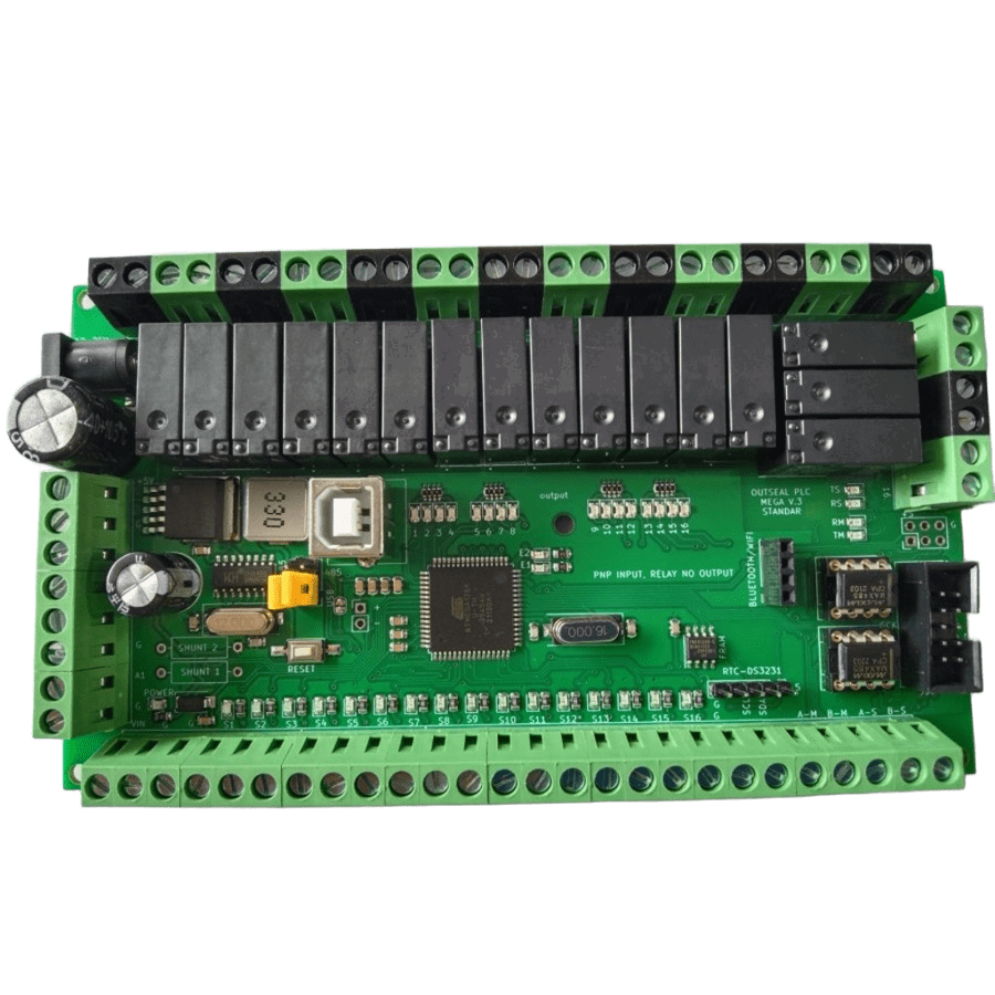
 Design with Outseal PLC Mega V.3 Standar in Cirkit Designer
Introduction
The Outseal PLC Mega V.3 Standar is a programmable logic controller (PLC) designed for automation and control applications. It features multiple input/output (I/O) channels, robust processing capabilities, and user-friendly programming interfaces, making it an ideal choice for industrial, commercial, and educational projects. This PLC is engineered to handle complex automation tasks with high reliability and precision.
Explore Projects Built with Outseal PLC Mega V.3 Standar
 Open Project in Cirkit Designer
 Open Project in Cirkit Designer
 Open Project in Cirkit Designer
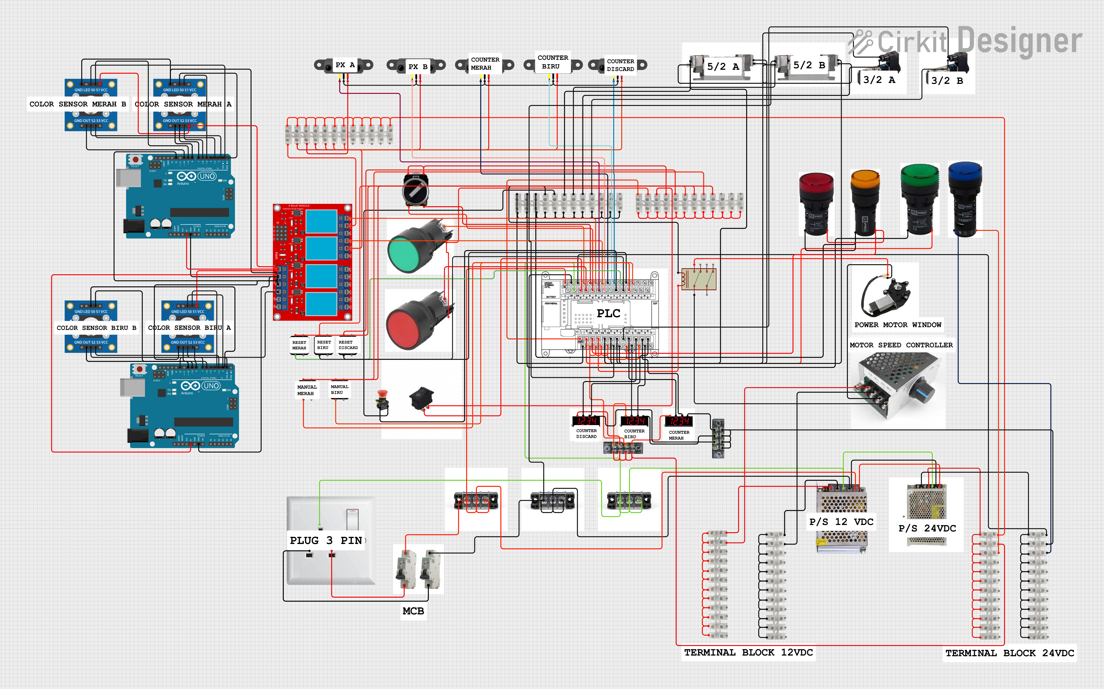 Open Project in Cirkit Designer
Explore Projects Built with Outseal PLC Mega V.3 Standar
Open Project in Cirkit DesignerOpen Project in Cirkit DesignerOpen Project in Cirkit DesignerOpen Project in Cirkit DesignerCommon Applications and Use Cases
- Industrial automation and process control
- Smart home systems and building automation
- Conveyor belt and motor control systems
- Data acquisition and monitoring
- Educational projects for learning PLC programming
- Integration with sensors, actuators, and other control devices
Technical Specifications
The following table outlines the key technical details of the Outseal PLC Mega V.3 Standar:
| Specification | Details |
|---|---|
| Processor | 32-bit ARM Cortex-M4 |
| Operating Voltage | 24V DC |
| Input Voltage Range | 12V to 24V DC |
| Digital Inputs | 16 channels (optically isolated) |
| Digital Outputs | 16 channels (relay and transistor) |
| Analog Inputs | 8 channels (0-10V, 12-bit ADC) |
| Analog Outputs | 4 channels (0-10V, 12-bit DAC) |
| Communication Ports | RS485, Ethernet, USB, CAN |
| Programming Interface | Ladder Logic, Function Block, C |
| Memory | 256 KB Flash, 64 KB RAM |
| Operating Temperature | -20°C to 70°C |
| Dimensions | 150mm x 90mm x 60mm |
| Mounting | DIN Rail |
Pin Configuration and Descriptions
The following table provides details about the pin configuration for the I/O terminals:
Digital Inputs
| Pin | Label | Description |
|---|---|---|
| 1 | DI1 | Digital Input 1 |
| 2 | DI2 | Digital Input 2 |
| ... | ... | ... |
| 16 | DI16 | Digital Input 16 |
Digital Outputs
| Pin | Label | Description |
|---|---|---|
| 1 | DO1 | Digital Output 1 (Relay) |
| 2 | DO2 | Digital Output 2 (Relay) |
| ... | ... | ... |
| 16 | DO16 | Digital Output 16 (Transistor) |
Analog Inputs and Outputs
| Pin | Label | Description |
|---|---|---|
| 1 | AI1 | Analog Input 1 (0-10V) |
| 2 | AI2 | Analog Input 2 (0-10V) |
| ... | ... | ... |
| 8 | AI8 | Analog Input 8 (0-10V) |
| 9 | AO1 | Analog Output 1 (0-10V) |
| 10 | AO2 | Analog Output 2 (0-10V) |
| ... | ... | ... |
| 12 | AO4 | Analog Output 4 (0-10V) |
Usage Instructions
How to Use the Component in a Circuit
- Power Supply: Connect a 24V DC power supply to the PLC's power input terminals. Ensure the power supply is stable and within the specified voltage range.
- Digital Inputs: Connect sensors or switches to the digital input terminals. Ensure the input voltage levels match the PLC's specifications.
- Digital Outputs: Connect actuators, relays, or other devices to the digital output terminals. Verify the current and voltage ratings of the connected devices.
- Analog Inputs/Outputs: Use the analog input terminals for sensors that output 0-10V signals. Similarly, connect devices requiring 0-10V control signals to the analog output terminals.
- Communication: Use the RS485, Ethernet, USB, or CAN ports to interface with other devices or systems. Configure the communication settings as needed.
- Programming: Use the provided software to program the PLC using Ladder Logic, Function Block, or C. Upload the program to the PLC via the USB or Ethernet port.
Important Considerations and Best Practices
- Always ensure proper grounding to avoid electrical noise and interference.
- Use optically isolated inputs for high-voltage or noisy environments.
- Avoid exceeding the maximum current and voltage ratings for the I/O channels.
- Regularly update the PLC firmware to ensure compatibility with the latest software features.
- Use proper cable management to prevent accidental disconnections or short circuits.
Example Code for Arduino UNO Integration
The Outseal PLC Mega V.3 Standar can communicate with an Arduino UNO via RS485. Below is an example code snippet for sending data from the Arduino to the PLC:
#include <ModbusMaster.h>

// Instantiate ModbusMaster object
ModbusMaster node;

void setup() {
  Serial.begin(9600); // Initialize serial communication
  node.begin(1, Serial); // Set Modbus slave ID to 1
}

void loop() {
  uint8_t result;

  // Write a value to a holding register (e.g., register 100)
  result = node.writeSingleRegister(100, 1234);

  if (result == node.ku8MBSuccess) {
    // Successfully wrote to the register
    Serial.println("Data sent to PLC successfully!");
  } else {
    // Handle communication error
    Serial.println("Error sending data to PLC.");
  }

  delay(1000); // Wait 1 second before sending the next command
}
Notes:
- Ensure the RS485 module is properly connected between the Arduino and the PLC.
- Match the baud rate and communication settings on both devices.
Troubleshooting and FAQs
Common Issues Users Might Face
PLC Not Powering On:
- Check the power supply voltage and connections.
- Ensure the power supply provides sufficient current.
Inputs Not Responding:
- Verify the input voltage levels match the PLC's specifications.
- Check for loose or faulty connections.
Outputs Not Activating:
- Ensure the connected devices are within the output channel's voltage and current ratings.
- Check the program logic for errors.
Communication Failure:
- Verify the communication settings (baud rate, parity, etc.) on both the PLC and the connected device.
- Check the wiring and ensure proper termination for RS485 connections.
Solutions and Tips for Troubleshooting
- Use a multimeter to check voltage levels at the input and output terminals.
- Test the PLC with a simple program to isolate hardware issues.
- Refer to the user manual for detailed error codes and diagnostic procedures.
- Contact technical support if the issue persists after following the troubleshooting steps.
By following this documentation, users can effectively utilize the Outseal PLC Mega V.3 Standar for a wide range of automation and control applications.