How to Use CTVIB01 0-10V to 4-20mA Converter: Examples, Pinouts, and Specs
Introduction
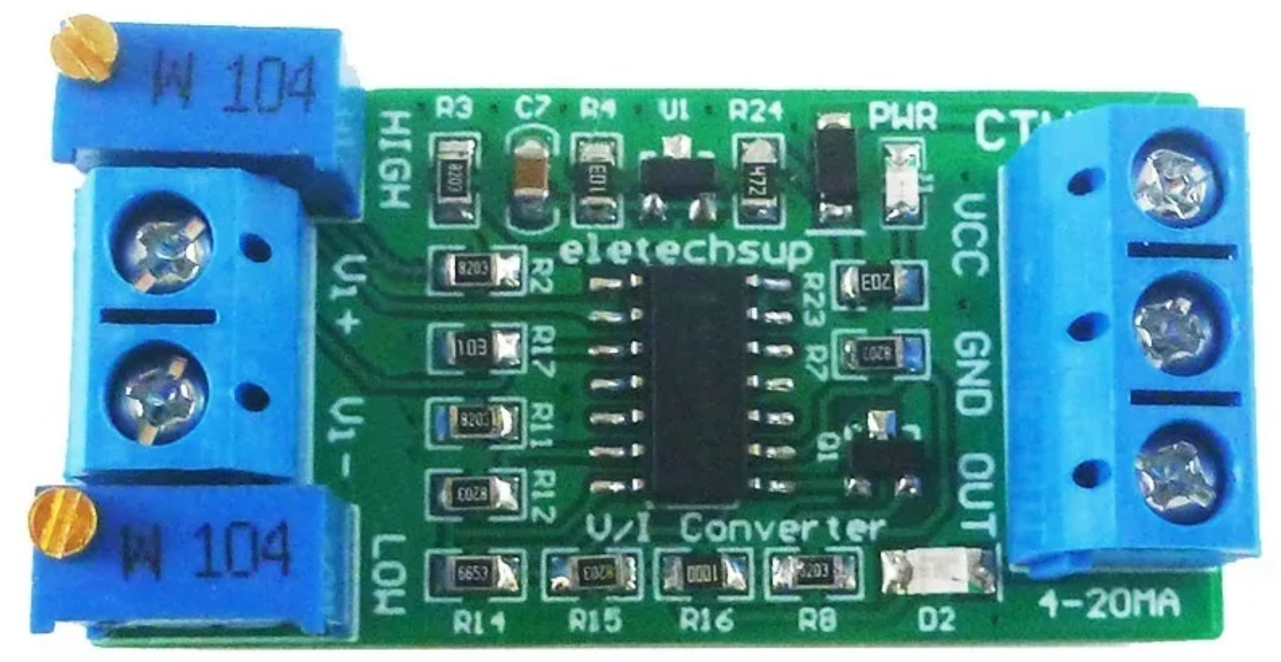
The CTVIB01 is a precision signal converter manufactured by ELETECHSUP. It is designed to convert a 0-10V analog voltage signal into a 4-20mA current signal. This conversion is essential in industrial automation and control systems, where current signals are preferred for their resilience to noise and ability to transmit data over long distances without significant signal degradation.
Explore Projects Built with CTVIB01 0-10V to 4-20mA Converter


Explore Projects Built with CTVIB01 0-10V to 4-20mA Converter
Common Applications and Use Cases
- Industrial Automation: Transmitting sensor data (e.g., temperature, pressure, or flow) to a PLC or control system.
- Process Control: Converting voltage signals from controllers or sensors into current signals for actuators or indicators.
- Remote Monitoring: Sending analog signals over long distances in noisy environments.
- Signal Standardization: Ensuring compatibility between devices that use different signal standards.
Technical Specifications
The following table outlines the key technical details of the CTVIB01:
| Parameter | Specification |
|---|---|
| Input Voltage Range | 0-10V DC |
| Output Current Range | 4-20mA DC |
| Power Supply Voltage | 12-24V DC |
| Accuracy | ±0.1% of full scale |
| Operating Temperature | -20°C to 70°C |
| Input Impedance | ≥ 100kΩ |
| Output Load Resistance | ≤ 500Ω |
| Dimensions | 75mm x 25mm x 50mm |
| Mounting Type | DIN Rail |
Pin Configuration and Descriptions
The CTVIB01 has a simple pin layout for easy integration into circuits. The pin configuration is as follows:
| Pin Number | Label | Description |
|---|---|---|
| 1 | V+ | Positive terminal for power supply (12-24V DC) |
| 2 | V- | Negative terminal for power supply (GND) |
| 3 | IN+ | Positive terminal for 0-10V input signal |
| 4 | IN- | Negative terminal for 0-10V input signal (GND) |
| 5 | OUT+ | Positive terminal for 4-20mA output signal |
| 6 | OUT- | Negative terminal for 4-20mA output signal (GND) |
Usage Instructions
How to Use the CTVIB01 in a Circuit
- Power Supply: Connect a 12-24V DC power supply to the
V+andV-pins. Ensure the power supply is stable and within the specified range. - Input Signal: Connect the 0-10V analog signal source (e.g., a sensor or controller) to the
IN+andIN-pins. Ensure the signal source is properly grounded. - Output Signal: Connect the
OUT+andOUT-pins to the device that accepts a 4-20mA current signal (e.g., a PLC, actuator, or indicator). Verify that the load resistance does not exceed 500Ω. - Calibration (if required): Some applications may require fine-tuning of the output signal. Refer to the manufacturer's calibration procedure if adjustments are needed.
Important Considerations and Best Practices
- Power Supply: Use a regulated DC power supply to avoid fluctuations that could affect signal accuracy.
- Grounding: Ensure all devices in the circuit share a common ground to prevent ground loops and signal interference.
- Load Resistance: Keep the load resistance within the specified range (≤ 500Ω) to ensure proper operation.
- Signal Integrity: Use shielded cables for the input and output connections in noisy environments to minimize interference.
- Temperature: Operate the device within the specified temperature range (-20°C to 70°C) to maintain accuracy and reliability.
Example: Connecting to an Arduino UNO
The CTVIB01 can be used with an Arduino UNO to read a 0-10V sensor and transmit the data as a 4-20mA signal. Below is an example circuit and code:
Circuit Diagram
- Connect the sensor's 0-10V output to the
IN+andIN-pins of the CTVIB01. - Connect the
OUT+andOUT-pins to a 4-20mA receiver or load. - Power the CTVIB01 with a 12-24V DC power supply.
Arduino Code
// Example code for reading a 0-10V sensor and transmitting a 4-20mA signal
// Ensure the sensor is connected to the CTVIB01, and the output is connected
// to a 4-20mA receiver.

const int sensorPin = A0; // Analog pin connected to the 0-10V sensor
float sensorValue = 0;    // Variable to store the sensor reading
float voltage = 0;        // Variable to store the calculated voltage

void setup() {
  Serial.begin(9600); // Initialize serial communication for debugging
}

void loop() {
  // Read the analog value from the sensor (0-1023 for 0-5V on Arduino UNO)
  sensorValue = analogRead(sensorPin);

  // Convert the analog reading to a voltage (assuming a 5V reference)
  voltage = (sensorValue / 1023.0) * 10.0; // Scale to 0-10V range

  // Print the voltage to the Serial Monitor
  Serial.print("Sensor Voltage: ");
  Serial.print(voltage);
  Serial.println(" V");

  // The CTVIB01 will automatically convert the 0-10V signal to 4-20mA
  // No additional code is required for the conversion.

  delay(1000); // Wait for 1 second before the next reading
}
Troubleshooting and FAQs
Common Issues and Solutions
No Output Signal
- Cause: Power supply not connected or incorrect voltage.
- Solution: Verify the power supply connections and ensure the voltage is within the 12-24V range.
Incorrect Output Current
- Cause: Input signal is out of range or improperly connected.
- Solution: Check the input signal source and ensure it is within the 0-10V range. Verify the connections to
IN+andIN-.
Signal Noise or Interference
- Cause: Unshielded cables or ground loops.
- Solution: Use shielded cables and ensure all devices share a common ground.
Overheating
- Cause: Operating outside the specified temperature range or excessive load resistance.
- Solution: Ensure the ambient temperature is within -20°C to 70°C and the load resistance is ≤ 500Ω.
FAQs
Q: Can the CTVIB01 handle input signals above 10V?
A: No, the input signal must be within the 0-10V range. Signals above 10V may damage the device.
Q: Is the CTVIB01 compatible with 3.3V systems?
A: The CTVIB01 requires a 12-24V DC power supply. However, it can convert a 0-10V signal generated by a 3.3V system if properly scaled.
Q: Can I use the CTVIB01 in outdoor environments?
A: The CTVIB01 is not weatherproof. Use it in a protected enclosure if operating in outdoor or harsh environments.