Cirkit Designer Logo
Cirkit Designer
Your all-in-one circuit design IDE
Home / 
Component Documentation

How to Use SY8205 : Examples, Pinouts, and Specs

Image of SY8205
Cirkit Designer LogoDesign with SY8205 in Cirkit Designer

Introduction

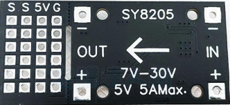
The SY8205 is a high-efficiency step-down (buck) DC-DC converter designed for low-power applications. It is capable of converting a higher input voltage to a lower, stable output voltage with high efficiency. The SY8205 features a wide input voltage range, adjustable output voltage, and built-in protection mechanisms such as overcurrent protection and thermal shutdown. These features make it a reliable choice for powering microcontrollers, sensors, and other electronic devices in portable and embedded systems.

Explore Projects Built with SY8205

Use Cirkit Designer to design, explore, and prototype these projects online. Some projects support real-time simulation. Click "Open Project" to start designing instantly!
Satellite-Based Timing and Navigation System with SDR and Atomic Clock Synchronization
Image of GPS 시스템 측정 구성도_Confirm: A project utilizing SY8205  in a practical application
This circuit appears to be a complex system involving power supply management, GPS and timing synchronization, and data communication. It includes a SI-TEX G1 Satellite Compass for GPS data, an XHTF1021 Atomic Rubidium Clock for precise timing, and Ettus USRP B200 units for software-defined radio communication. Power is supplied through various SMPS units and distributed via terminal blocks and DC jacks. Data communication is facilitated by Beelink MINI S12 N95 computers, RS232 splitters, and a 1000BASE-T Media Converter for network connectivity. RF Directional Couplers are used to interface antennas with the USRP units, and the entire system is likely contained within cases for protection and organization.
Cirkit Designer LogoOpen Project in Cirkit Designer
Arduino Mega 2560 Based Security System with Fingerprint Authentication and SMS Alerts
Image of Door security system: A project utilizing SY8205  in a practical application
This circuit features an Arduino Mega 2560 microcontroller interfaced with a SIM800L GSM module, two fingerprint scanners, an I2C LCD display, an IR sensor, and a piezo buzzer. Power management is handled by a PowerBoost 1000 Basic Pad USB, a TP4056 charging module, and a Li-ion 18650 battery, with an option to use a Mini AC-DC 110V-230V to 5V 700mA module for direct power supply. The primary functionality appears to be a security system with GSM communication capabilities, biometric access control, and visual/audible feedback.
Cirkit Designer LogoOpen Project in Cirkit Designer
Battery-Powered Raspberry Pi Pico GPS Tracker with Sensor Integration
Image of Copy of CanSet v1: A project utilizing SY8205  in a practical application
This circuit is a data acquisition and communication system powered by a LiPoly battery and managed by a Raspberry Pi Pico. It includes sensors (BMP280, MPU9250) for environmental data, a GPS module for location tracking, an SD card for data storage, and a WLR089-CanSAT for wireless communication. The TP4056 module handles battery charging, and a toggle switch controls power distribution.
Cirkit Designer LogoOpen Project in Cirkit Designer
Battery-Powered Emergency Alert System with NUCLEO-F072RB, SIM800L, and GPS NEO 6M
Image of women safety: A project utilizing SY8205  in a practical application
This circuit is an emergency alert system that uses a NUCLEO-F072RB microcontroller to send SMS alerts and make calls via a SIM800L GSM module, while obtaining location data from a GPS NEO 6M module. The system is powered by a Li-ion battery and includes a TP4056 module for battery charging and protection, with a rocker switch to control power to the microcontroller.
Cirkit Designer LogoOpen Project in Cirkit Designer

Explore Projects Built with SY8205

Use Cirkit Designer to design, explore, and prototype these projects online. Some projects support real-time simulation. Click "Open Project" to start designing instantly!
Image of GPS 시스템 측정 구성도_Confirm: A project utilizing SY8205  in a practical application
Satellite-Based Timing and Navigation System with SDR and Atomic Clock Synchronization
This circuit appears to be a complex system involving power supply management, GPS and timing synchronization, and data communication. It includes a SI-TEX G1 Satellite Compass for GPS data, an XHTF1021 Atomic Rubidium Clock for precise timing, and Ettus USRP B200 units for software-defined radio communication. Power is supplied through various SMPS units and distributed via terminal blocks and DC jacks. Data communication is facilitated by Beelink MINI S12 N95 computers, RS232 splitters, and a 1000BASE-T Media Converter for network connectivity. RF Directional Couplers are used to interface antennas with the USRP units, and the entire system is likely contained within cases for protection and organization.
Cirkit Designer LogoOpen Project in Cirkit Designer
Image of Door security system: A project utilizing SY8205  in a practical application
Arduino Mega 2560 Based Security System with Fingerprint Authentication and SMS Alerts
This circuit features an Arduino Mega 2560 microcontroller interfaced with a SIM800L GSM module, two fingerprint scanners, an I2C LCD display, an IR sensor, and a piezo buzzer. Power management is handled by a PowerBoost 1000 Basic Pad USB, a TP4056 charging module, and a Li-ion 18650 battery, with an option to use a Mini AC-DC 110V-230V to 5V 700mA module for direct power supply. The primary functionality appears to be a security system with GSM communication capabilities, biometric access control, and visual/audible feedback.
Cirkit Designer LogoOpen Project in Cirkit Designer
Image of Copy of CanSet v1: A project utilizing SY8205  in a practical application
Battery-Powered Raspberry Pi Pico GPS Tracker with Sensor Integration
This circuit is a data acquisition and communication system powered by a LiPoly battery and managed by a Raspberry Pi Pico. It includes sensors (BMP280, MPU9250) for environmental data, a GPS module for location tracking, an SD card for data storage, and a WLR089-CanSAT for wireless communication. The TP4056 module handles battery charging, and a toggle switch controls power distribution.
Cirkit Designer LogoOpen Project in Cirkit Designer
Image of women safety: A project utilizing SY8205  in a practical application
Battery-Powered Emergency Alert System with NUCLEO-F072RB, SIM800L, and GPS NEO 6M
This circuit is an emergency alert system that uses a NUCLEO-F072RB microcontroller to send SMS alerts and make calls via a SIM800L GSM module, while obtaining location data from a GPS NEO 6M module. The system is powered by a Li-ion battery and includes a TP4056 module for battery charging and protection, with a rocker switch to control power to the microcontroller.
Cirkit Designer LogoOpen Project in Cirkit Designer

Common Applications

  • Powering microcontrollers and sensors in embedded systems
  • Battery-powered devices
  • Consumer electronics
  • Industrial control systems
  • IoT devices

Technical Specifications

Key Specifications

Parameter Value
Input Voltage Range 4.5V to 18V
Output Voltage Range Adjustable (0.6V to 15V)
Output Current Up to 3A
Switching Frequency 500kHz
Efficiency Up to 95%
Protection Features Overcurrent, thermal shutdown
Package Type SOT23-6

Pin Configuration and Descriptions

The SY8205 is available in a 6-pin SOT23-6 package. The pinout and descriptions are as follows:

Pin Number Pin Name Description
1 VIN Input voltage pin. Connect to the input power supply (4.5V to 18V).
2 GND Ground pin. Connect to the system ground.
3 SW Switching node. Connect to the inductor and output capacitor.
4 FB Feedback pin. Connect to a resistor divider to set the output voltage.
5 EN Enable pin. Drive high to enable the converter, low to disable it.
6 BST Bootstrap pin. Connect a capacitor (typically 0.1µF) between BST and SW.

Usage Instructions

How to Use the SY8205 in a Circuit

  1. Input Voltage: Ensure the input voltage is within the range of 4.5V to 18V.
  2. Output Voltage Setting: Use a resistor divider network connected to the FB pin to set the desired output voltage. The output voltage can be calculated using the formula: [ V_{OUT} = V_{REF} \times \left(1 + \frac{R1}{R2}\right) ] where ( V_{REF} ) is 0.6V, ( R1 ) is the resistor connected between FB and VOUT, and ( R2 ) is the resistor connected between FB and GND.
  3. Inductor Selection: Choose an inductor with a current rating higher than the maximum output current (3A) and an appropriate inductance value to ensure stable operation.
  4. Capacitor Selection: Use low-ESR capacitors for input and output filtering. Typical values are:
    • Input capacitor: 10µF to 22µF
    • Output capacitor: 22µF to 47µF
  5. Bootstrap Capacitor: Connect a 0.1µF ceramic capacitor between the BST and SW pins.
  6. Enable Pin: Drive the EN pin high (logic level) to enable the converter. Pull it low to disable the converter.

Example Circuit

Below is an example of a basic SY8205 circuit configuration:

VIN (4.5V-18V) ----+----+----+----+----+----+----+----+----+----+----+----+
                   |    |    |    |    |    |    |    |    |    |    |    |
                  [CIN] [L]  [R1] [R2] [COUT] [BST] [SW] [FB] [EN] [GND] 

Arduino UNO Example Code

The SY8205 can be used to power an Arduino UNO. Below is an example code snippet to control the EN pin of the SY8205 using a digital output pin of the Arduino:

// Define the pin connected to the SY8205 EN pin
const int enablePin = 7;

void setup() {
  // Set the enable pin as an output
  pinMode(enablePin, OUTPUT);

  // Enable the SY8205 by setting the pin HIGH
  digitalWrite(enablePin, HIGH);
}

void loop() {
  // The SY8205 remains enabled in this example
  // Add your application code here
}

Important Considerations

  • Ensure proper heat dissipation, especially when operating at high currents.
  • Use short and wide traces for the power path to minimize resistance and improve efficiency.
  • Place the input and output capacitors as close as possible to the VIN, GND, and SW pins to reduce noise and improve stability.

Troubleshooting and FAQs

Common Issues and Solutions

Issue Possible Cause Solution
No output voltage EN pin is not driven high Check the EN pin connection and ensure it is set to a logic HIGH level.
Output voltage is incorrect Incorrect resistor divider values Verify the resistor values and recalculate the output voltage.
Overheating Excessive load current or poor layout Reduce the load current or improve PCB layout for better heat dissipation.
High output ripple Insufficient output capacitance Increase the output capacitor value or use low-ESR capacitors.
Device shuts down unexpectedly Overcurrent or thermal protection active Check the load current and ensure proper cooling.

FAQs

  1. Can the SY8205 operate with a 3.3V input?

    • No, the minimum input voltage is 4.5V.
  2. What is the maximum output current?

    • The SY8205 can deliver up to 3A of output current.
  3. How do I calculate the output voltage?

    • Use the formula ( V_{OUT} = V_{REF} \times (1 + R1/R2) ), where ( V_{REF} = 0.6V ).
  4. Can I leave the EN pin floating?

    • No, the EN pin must be driven high or low. Floating the pin may cause unpredictable behavior.

By following this documentation, you can effectively integrate the SY8205 into your projects and troubleshoot common issues.