How to Use NO Touch Switch: Examples, Pinouts, and Specs
Introduction
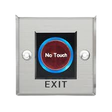
A Normally Open (NO) Touch Switch is an electronic switch that operates by touch. When the switch is touched, it closes the circuit, allowing current to flow. This type of switch is widely used in applications requiring a touch-sensitive interface, such as lighting controls, home automation systems, and electronic devices. Its simplicity and reliability make it a popular choice for modern touch-based designs.
Explore Projects Built with NO Touch Switch

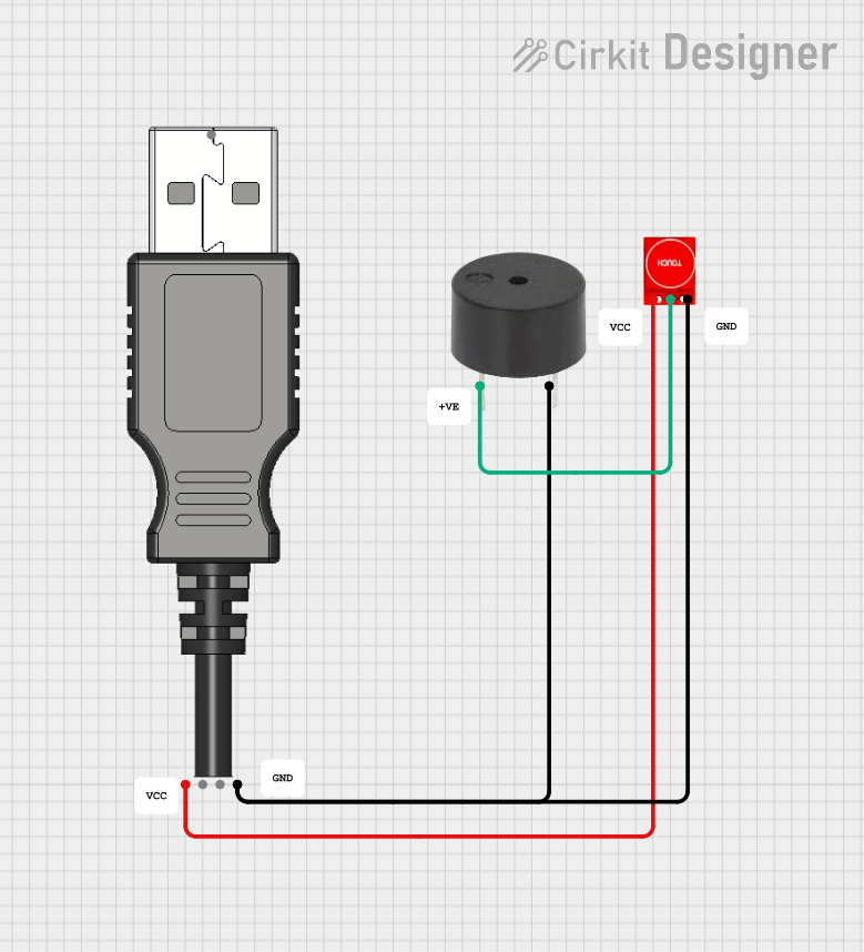

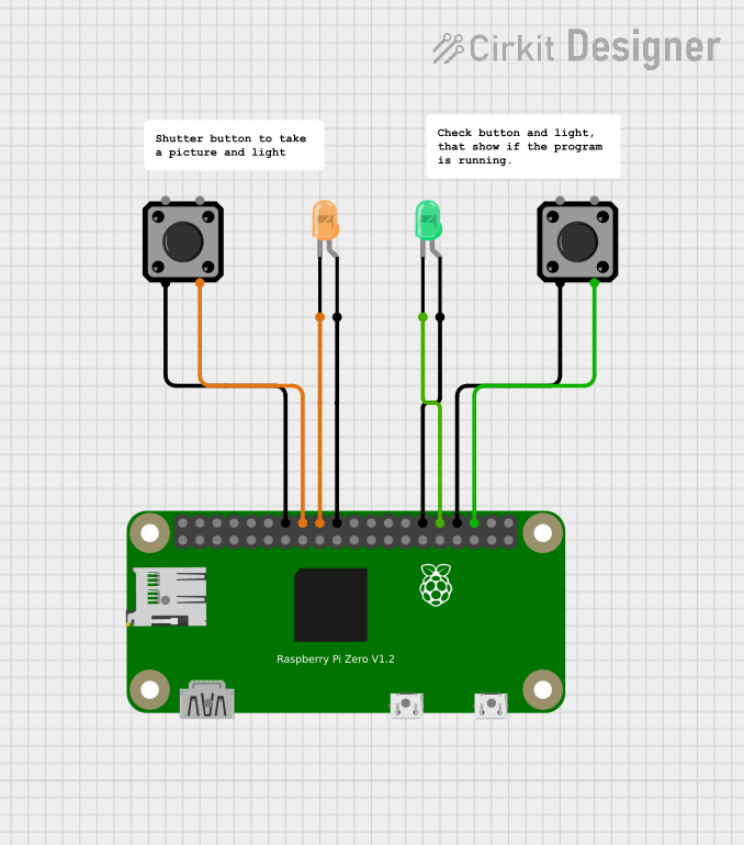
Explore Projects Built with NO Touch Switch
Technical Specifications
- Type: Normally Open (NO) Touch Switch
- Operating Voltage: 3.3V to 5V DC
- Operating Current: ≤ 10mA
- Output Type: Digital (High when touched, Low when not touched)
- Response Time: < 60ms
- Operating Temperature: -20°C to 70°C
- Dimensions: Varies by model, typically compact for PCB mounting
Pin Configuration and Descriptions
The NO Touch Switch typically has three pins. Below is the pinout description:
| Pin | Name | Description |
|---|---|---|
| 1 | VCC | Power supply pin. Connect to 3.3V or 5V DC. |
| 2 | GND | Ground pin. Connect to the ground of the circuit. |
| 3 | OUT | Digital output pin. Outputs HIGH (1) when touched and LOW (0) when not touched. |
Usage Instructions
How to Use the NO Touch Switch in a Circuit
- Power the Switch: Connect the
VCCpin to a 3.3V or 5V DC power source and theGNDpin to the ground of your circuit. - Connect the Output: Connect the
OUTpin to the input of a microcontroller (e.g., Arduino) or to another circuit component that requires a digital signal. - Touch to Operate: When the touch-sensitive area of the switch is touched, the
OUTpin will output a HIGH signal. When not touched, the output will remain LOW.
Important Considerations and Best Practices
- Debouncing: The switch may produce noise or multiple signals when touched. Use software debouncing in your microcontroller code to ensure stable operation.
- Voltage Compatibility: Ensure the operating voltage of the switch matches the voltage level of your circuit to avoid damage.
- Environmental Factors: Avoid exposing the switch to moisture or extreme temperatures, as this may affect its performance.
- Pull-Down Resistor: If the output pin is connected to a microcontroller, consider using a pull-down resistor to ensure the output remains LOW when not touched.
Example: Connecting the NO Touch Switch to an Arduino UNO
Below is an example of how to connect and use the NO Touch Switch with an Arduino UNO:
Circuit Diagram
- Connect the
VCCpin of the switch to the 5V pin on the Arduino. - Connect the
GNDpin of the switch to the GND pin on the Arduino. - Connect the
OUTpin of the switch to digital pin 2 on the Arduino.
Arduino Code
// Define the pin connected to the NO Touch Switch output
const int touchSwitchPin = 2;

// Define the pin for an LED (optional, for visual feedback)
const int ledPin = 13;

void setup() {
  // Set the touch switch pin as input
  pinMode(touchSwitchPin, INPUT);

  // Set the LED pin as output
  pinMode(ledPin, OUTPUT);

  // Initialize serial communication for debugging
  Serial.begin(9600);
}

void loop() {
  // Read the state of the touch switch
  int touchState = digitalRead(touchSwitchPin);

  // Print the state to the Serial Monitor
  Serial.println(touchState);

  // If the switch is touched, turn on the LED
  if (touchState == HIGH) {
    digitalWrite(ledPin, HIGH); // Turn on the LED
  } else {
    digitalWrite(ledPin, LOW);  // Turn off the LED
  }

  // Add a small delay to stabilize the loop
  delay(50);
}
Troubleshooting and FAQs
Common Issues and Solutions
The switch does not respond to touch.
- Ensure the
VCCandGNDpins are properly connected to the power supply. - Verify that the operating voltage matches the switch's specifications.
- Check for loose or faulty connections in the circuit.
- Ensure the
The output signal is unstable or noisy.
- Implement software debouncing in your microcontroller code to filter out noise.
- Ensure the switch is not exposed to electrical interference or static.
The switch triggers without being touched.
- Check for environmental factors such as moisture or dirt on the touch-sensitive area.
- Verify that the circuit is properly grounded.
The switch output is always LOW.
- Confirm that the
OUTpin is correctly connected to the microcontroller or circuit. - Test the switch with a multimeter to ensure it is functioning correctly.
- Confirm that the
FAQs
Q: Can the NO Touch Switch be used with a 3.3V system?
A: Yes, the switch is compatible with both 3.3V and 5V systems. Ensure the VCC pin is connected to the appropriate voltage.
Q: Is the switch waterproof?
A: Most NO Touch Switches are not waterproof. Avoid exposing the switch to moisture or liquids.
Q: Can I use the switch to control high-power devices?
A: No, the switch is designed for low-power digital signals. Use a relay or transistor to control high-power devices.
Q: How do I clean the touch-sensitive area?
A: Use a soft, dry cloth to clean the surface. Avoid using liquids or abrasive materials.