
How to Use EML: Examples, Pinouts, and Specs
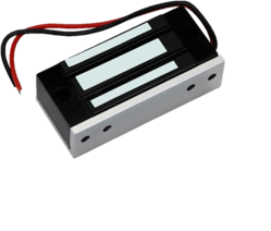
 Design with EML in Cirkit Designer
Introduction
The Electroabsorption Modulated Laser (EML) is a sophisticated component used primarily in fiber optic communications. It converts electrical signals into optical signals, enabling high-speed data transmission over long distances. EMLs are integral to modern telecommunications, data centers, and high-speed internet infrastructure.
Explore Projects Built with EML
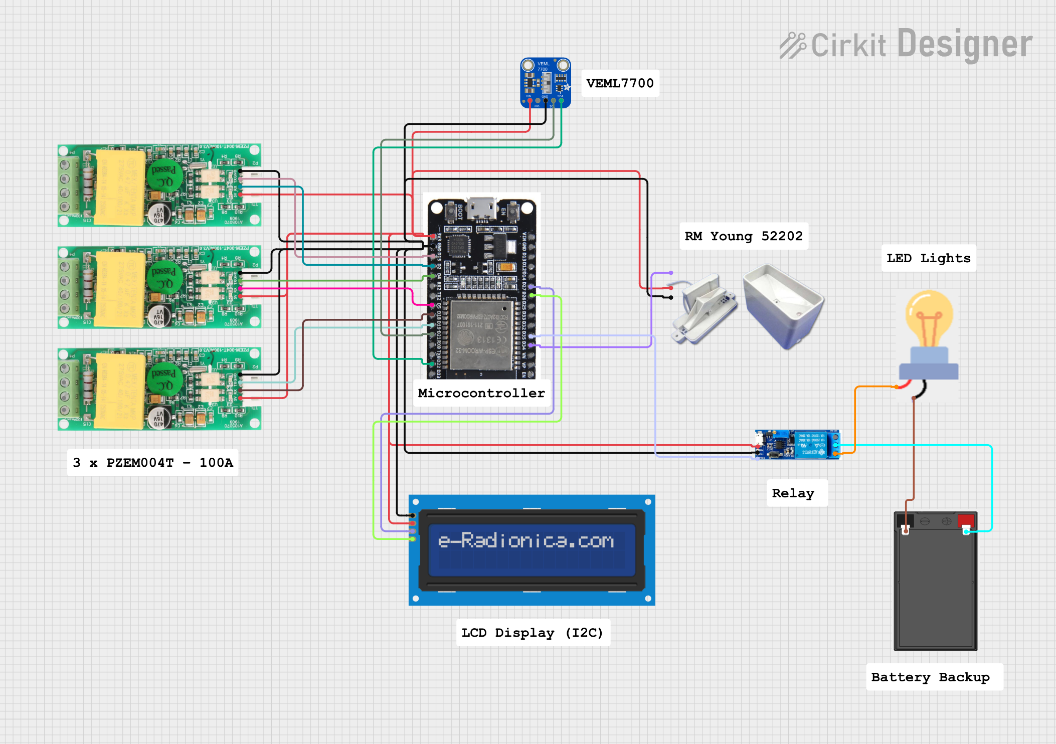
 Open Project in Cirkit Designer
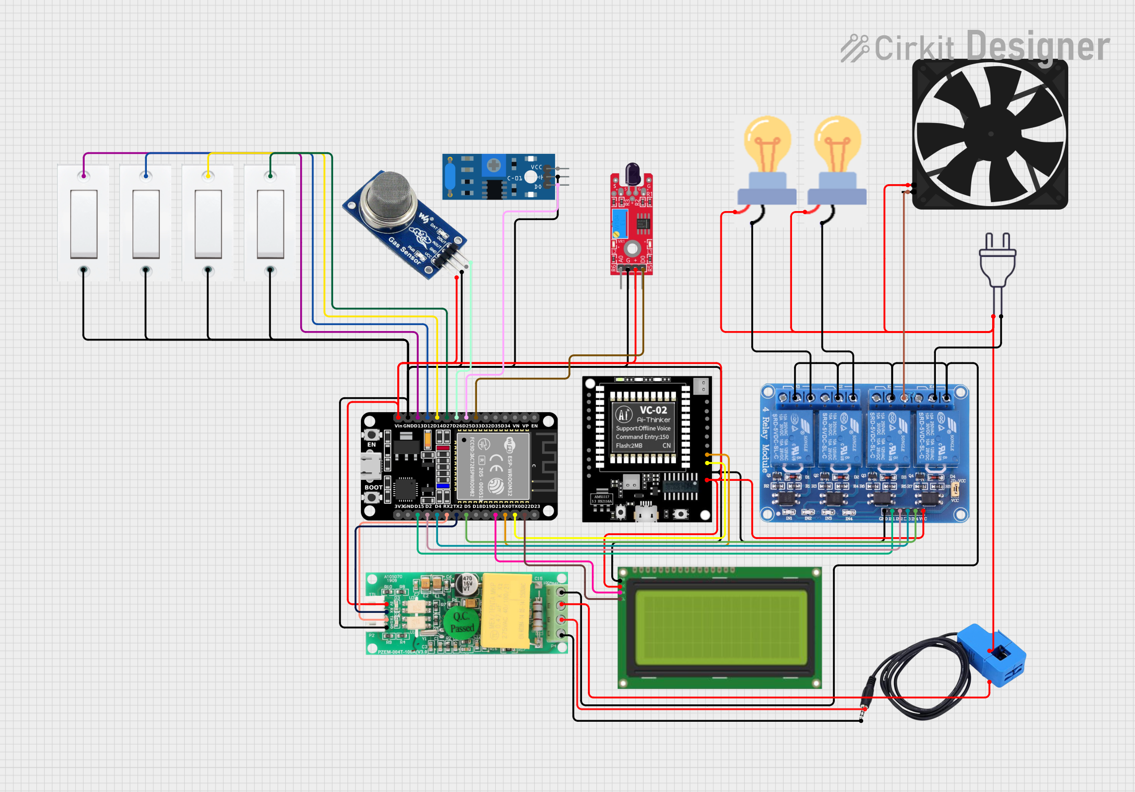
 Open Project in Cirkit Designer
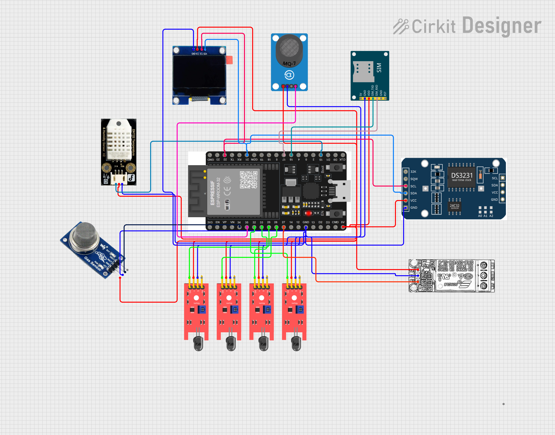
 Open Project in Cirkit Designer
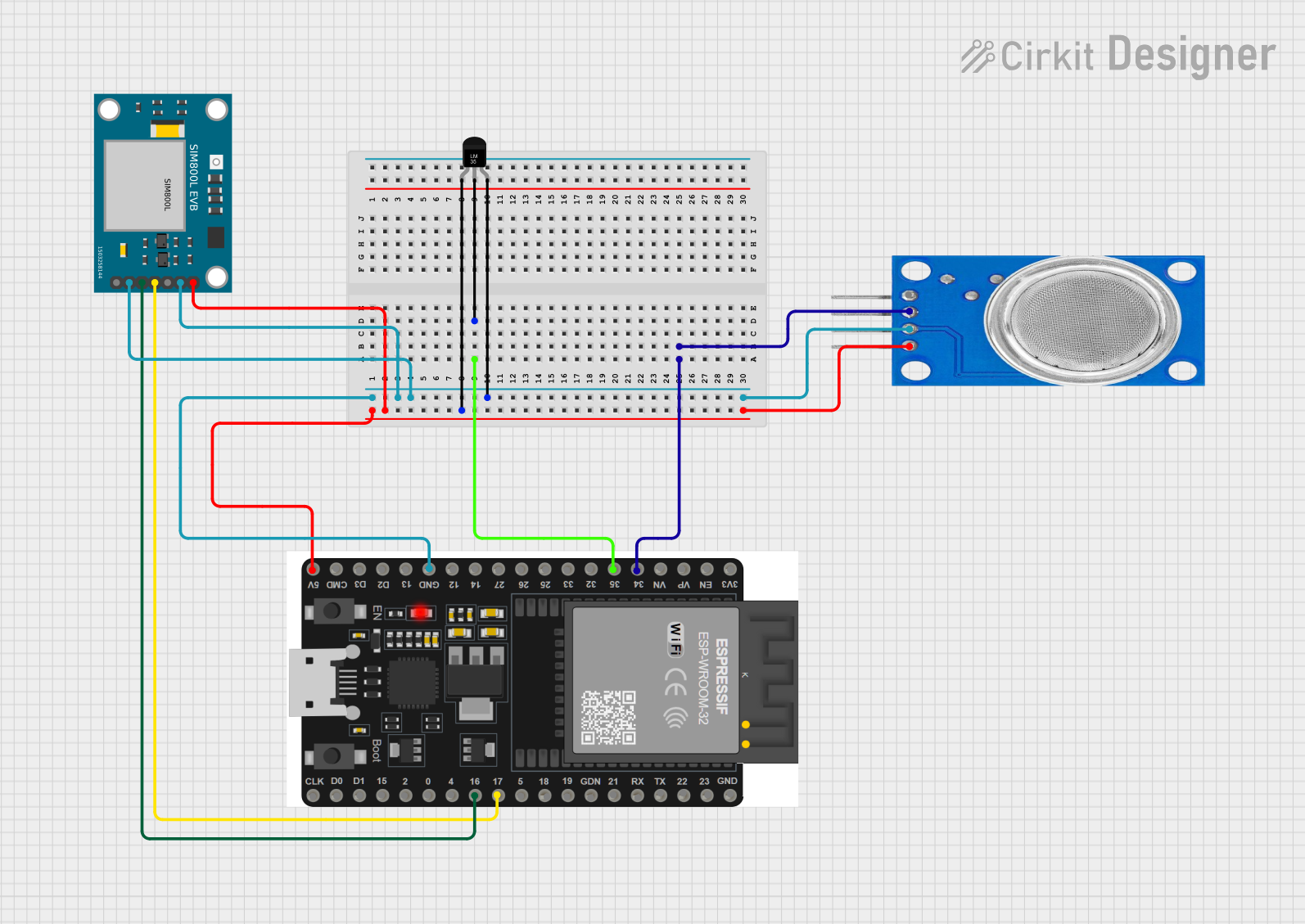
 Open Project in Cirkit Designer
Explore Projects Built with EML

 Open Project in Cirkit Designer
 Open Project in Cirkit Designer
 Open Project in Cirkit Designer
 Open Project in Cirkit Designer
Common Applications and Use Cases
- Telecommunications: EMLs are used in long-haul and metro fiber optic networks to transmit data over large distances with minimal signal degradation.
- Data Centers: They facilitate high-speed data transfer between servers and storage systems.
- High-Speed Internet: EMLs are crucial for providing high-speed internet services to end-users.
- Optical Networking: Used in various optical networking equipment for efficient data transmission.
Technical Specifications
Key Technical Details
| Parameter | Value |
|---|---|
| Operating Voltage | 3.3V |
| Operating Current | 100mA |
| Modulation Bandwidth | Up to 40 GHz |
| Wavelength Range | 1550 nm |
| Optical Output Power | 0 to 10 dBm |
| Temperature Range | -40°C to +85°C |
| Package Type | TO-56, Butterfly, or Custom |
Pin Configuration and Descriptions
| Pin Number | Pin Name | Description |
|---|---|---|
| 1 | Vcc | Supply Voltage (3.3V) |
| 2 | GND | Ground |
| 3 | Modulation In | Electrical signal input for modulation |
| 4 | Laser Anode | Positive terminal of the laser diode |
| 5 | Laser Cathode | Negative terminal of the laser diode |
| 6 | Monitor Diode | Photodiode for monitoring the laser output power |
Usage Instructions
How to Use the Component in a Circuit
- Power Supply: Connect the Vcc pin to a stable 3.3V power supply and the GND pin to the ground.
- Modulation Input: Feed the electrical signal to be converted into the Modulation In pin.
- Laser Connections: Connect the Laser Anode and Laser Cathode to the respective terminals of the laser diode.
- Monitor Diode: Use the Monitor Diode pin to monitor the optical output power and ensure the laser is operating correctly.
Important Considerations and Best Practices
- Heat Management: EMLs can generate significant heat. Ensure proper heat dissipation mechanisms, such as heat sinks or active cooling, are in place.
- Signal Integrity: Use high-quality cables and connectors to maintain signal integrity, especially for high-frequency modulation.
- Power Supply Stability: Ensure the power supply is stable and free from noise to prevent signal distortion.
- Safety: Handle the laser with care to avoid exposure to the laser beam, which can be harmful to the eyes.
Troubleshooting and FAQs
Common Issues and Solutions
No Optical Output:
- Check Power Supply: Ensure the Vcc and GND connections are correct and the power supply is stable.
- Verify Modulation Signal: Ensure the modulation signal is within the specified range and properly connected.
Low Optical Power:
- Monitor Diode Feedback: Check the monitor diode feedback to ensure the laser is operating correctly.
- Clean Connections: Ensure all optical and electrical connections are clean and secure.
Overheating:
- Improve Cooling: Enhance the cooling mechanism, such as adding a heat sink or improving airflow.
- Reduce Current: Ensure the operating current is within the specified range.
FAQs
Q: Can I use an EML with an Arduino UNO? A: Yes, you can use an EML with an Arduino UNO for basic modulation tasks. However, due to the high-frequency capabilities of the EML, ensure the modulation signal from the Arduino is within the EML's operating range.
Q: How do I monitor the optical output power? A: Use the Monitor Diode pin to measure the optical output power. Connect it to an appropriate monitoring circuit or device.
Q: What precautions should I take when handling the EML? A: Avoid direct exposure to the laser beam, ensure proper grounding to prevent static damage, and handle the component with care to avoid physical damage.
Example Code for Arduino UNO
// Example code to modulate an EML using Arduino UNO
// This example assumes a simple on/off modulation

const int modPin = 9; // Pin connected to Modulation In of EML

void setup() {
  pinMode(modPin, OUTPUT); // Set the modulation pin as output
}

void loop() {
  digitalWrite(modPin, HIGH); // Turn on the laser
  delay(1000); // Keep it on for 1 second
  digitalWrite(modPin, LOW); // Turn off the laser
  delay(1000); // Keep it off for 1 second
}
This example demonstrates a basic on/off modulation using the Arduino UNO. For more complex modulation schemes, consider using a high-speed signal generator or dedicated modulation circuitry.
This documentation provides a comprehensive overview of the Electroabsorption Modulated Laser (EML), including its technical specifications, usage instructions, and troubleshooting tips. Whether you are a beginner or an experienced user, this guide will help you effectively utilize the EML in your fiber optic communication projects.