How to Use dual 4-input OR gate integrated circuit: Examples, Pinouts, and Specs
Introduction
The CD4072B, manufactured by Texas Instruments, is a dual 4-input OR gate integrated circuit. This digital logic device contains two independent OR gates, each capable of accepting four input signals. The output of each gate is high (logic 1) if any of its inputs are high, making it a versatile component for implementing logical OR operations in digital circuits.
Explore Projects Built with dual 4-input OR gate integrated circuit


Explore Projects Built with dual 4-input OR gate integrated circuit
Common Applications and Use Cases
- Digital signal processing
- Logic level conversion
- Data routing and control
- Alarm and detection systems
- General-purpose logic circuits
The CD4072B is widely used in applications requiring compact and reliable logic functions, particularly in low-power systems.
Technical Specifications
Key Technical Details
| Parameter | Value |
|---|---|
| Supply Voltage (VDD) | 3V to 18V |
| Input Voltage Range | 0V to VDD |
| High-Level Output Voltage | Close to VDD (depending on load) |
| Low-Level Output Voltage | Close to 0V (depending on load) |
| Maximum Input Current | ±10 µA |
| Propagation Delay | ~60 ns at 10V |
| Power Dissipation | 500 mW (maximum) |
| Operating Temperature | -55°C to +125°C |
| Package Types | PDIP, SOIC, TSSOP, and others |
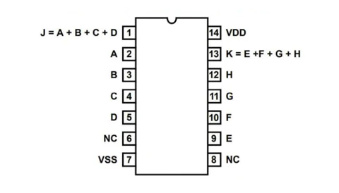
Pin Configuration and Descriptions
The CD4072B is typically available in a 14-pin dual in-line package (DIP). Below is the pinout and description:
| Pin Number | Pin Name | Description |
|---|---|---|
| 1 | A1 | Input A for OR Gate 1 |
| 2 | B1 | Input B for OR Gate 1 |
| 3 | C1 | Input C for OR Gate 1 |
| 4 | D1 | Input D for OR Gate 1 |
| 5 | Y1 | Output of OR Gate 1 |
| 6 | NC | No Connection |
| 7 | GND | Ground (0V reference) |
| 8 | Y2 | Output of OR Gate 2 |
| 9 | D2 | Input D for OR Gate 2 |
| 10 | C2 | Input C for OR Gate 2 |
| 11 | B2 | Input B for OR Gate 2 |
| 12 | A2 | Input A for OR Gate 2 |
| 13 | NC | No Connection |
| 14 | VDD | Positive Supply Voltage |
Usage Instructions
How to Use the Component in a Circuit
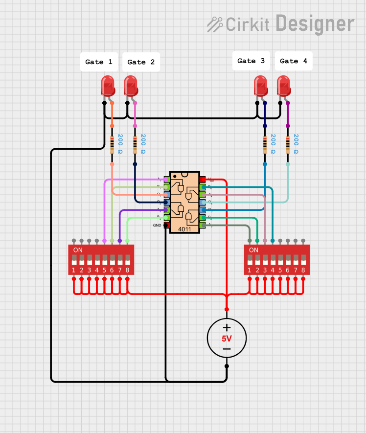
- Power Supply: Connect the VDD pin (pin 14) to a positive voltage source (3V to 18V) and the GND pin (pin 7) to ground.
- Inputs: Connect the input pins (A1, B1, C1, D1 for Gate 1; A2, B2, C2, D2 for Gate 2) to the desired logic signals.
- Outputs: The output pins (Y1 for Gate 1, Y2 for Gate 2) will provide a high signal (logic 1) if any of the corresponding inputs are high.
- Pull-Down Resistors: If any input is left unconnected, use pull-down resistors to ensure proper logic levels and avoid floating inputs.
Important Considerations and Best Practices
- Input Voltage Levels: Ensure that input voltages do not exceed the supply voltage (VDD) to prevent damage.
- Unused Inputs: Tie unused inputs to GND or VDD to avoid unpredictable behavior.
- Decoupling Capacitor: Place a 0.1 µF ceramic capacitor close to the VDD and GND pins to filter noise and stabilize the power supply.
- Load Considerations: Avoid exceeding the maximum output current to prevent damage to the IC.
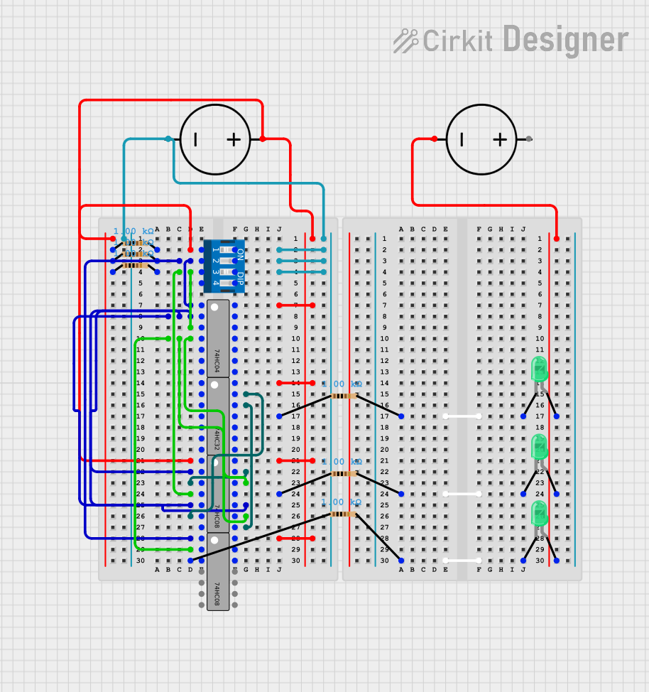
Example: Connecting to an Arduino UNO
The CD4072B can be interfaced with an Arduino UNO for digital logic operations. Below is an example of how to use the IC to process four digital inputs and output the result to an LED.
Circuit Connections
- Connect VDD (pin 14) to the Arduino's 5V pin and GND (pin 7) to the Arduino's GND.
- Connect four Arduino digital pins (e.g., D2, D3, D4, D5) to the inputs of OR Gate 1 (pins 1, 2, 3, 4).
- Connect the output of OR Gate 1 (pin 5) to another Arduino digital pin (e.g., D6) or directly to an LED with a current-limiting resistor.
Arduino Code
// Define input pins connected to the OR gate inputs
const int inputA = 2;
const int inputB = 3;
const int inputC = 4;
const int inputD = 5;

// Define output pin connected to the OR gate output
const int outputY = 6;

void setup() {
  // Set input pins as outputs to drive the OR gate
  pinMode(inputA, OUTPUT);
  pinMode(inputB, OUTPUT);
  pinMode(inputC, OUTPUT);
  pinMode(inputD, OUTPUT);

  // Set the output pin as input to read the OR gate output
  pinMode(outputY, INPUT);

  // Initialize all inputs to LOW
  digitalWrite(inputA, LOW);
  digitalWrite(inputB, LOW);
  digitalWrite(inputC, LOW);
  digitalWrite(inputD, LOW);
}

void loop() {
  // Example: Set some inputs HIGH to test the OR gate
  digitalWrite(inputA, HIGH);
  digitalWrite(inputB, LOW);
  digitalWrite(inputC, LOW);
  digitalWrite(inputD, HIGH);

  // Read the OR gate output
  int orOutput = digitalRead(outputY);

  // Use the output (e.g., turn on an LED if the output is HIGH)
  if (orOutput == HIGH) {
    // Perform some action, such as lighting an LED
  }
}
Troubleshooting and FAQs
Common Issues and Solutions
No Output Signal:
- Ensure the power supply is connected properly to VDD and GND.
- Verify that at least one input is high for the corresponding OR gate.
- Check for loose or incorrect connections.
Floating Inputs:
- Unconnected inputs can cause unpredictable behavior. Tie unused inputs to GND or VDD.
Output Voltage Too Low:
- Check if the load connected to the output exceeds the IC's drive capability.
- Verify the supply voltage is within the specified range.
Excessive Heat:
- Ensure the IC is not exposed to voltages or currents beyond its maximum ratings.
- Use proper decoupling capacitors to stabilize the power supply.
FAQs
Q: Can the CD4072B operate at 3.3V?
A: Yes, the CD4072B can operate with a supply voltage as low as 3V, making it compatible with 3.3V systems.
Q: What happens if all inputs are low?
A: The output of the OR gate will be low (logic 0) if all inputs are low.
Q: Can I use the CD4072B for analog signals?
A: No, the CD4072B is designed for digital logic signals and may not function correctly with analog inputs.
Q: How do I test the IC?
A: Apply known logic levels to the inputs and verify the output using an LED or a multimeter.
This concludes the documentation for the CD4072B Dual 4-Input OR Gate IC.