Cirkit Designer Logo
Cirkit Designer
Your all-in-one circuit design IDE
Home / 
Component Documentation

How to Use Adafruit 16-Channel 12-bit PWM Servo Shield - I2C: Examples, Pinouts, and Specs

Image of Adafruit 16-Channel 12-bit PWM Servo Shield - I2C
Cirkit Designer LogoDesign with Adafruit 16-Channel 12-bit PWM Servo Shield - I2C in Cirkit Designer

Introduction

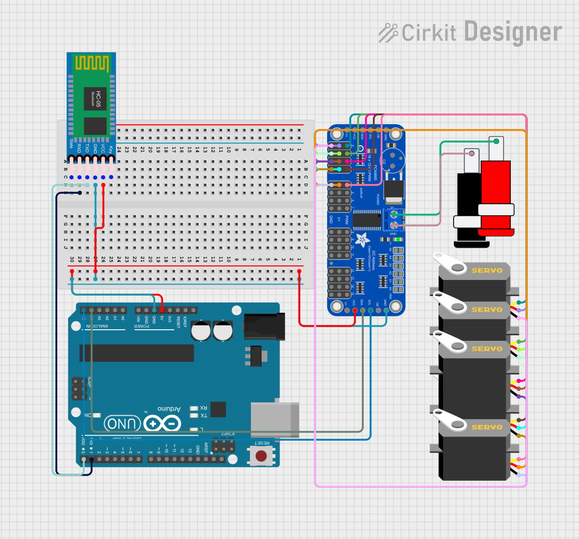
The Adafruit 16-Channel 12-bit PWM Servo Shield is an essential tool for hobbyists and engineers who need to control multiple servos simultaneously. This shield is designed to stack onto an Arduino UNO or similar microcontroller boards, providing an easy-to-use interface for controlling up to 16 servos with high precision thanks to its 12-bit resolution. Common applications include robotics, animatronics, custom RC vehicles, and any project requiring multiple servo controls.

Explore Projects Built with Adafruit 16-Channel 12-bit PWM Servo Shield - I2C

Use Cirkit Designer to design, explore, and prototype these projects online. Some projects support real-time simulation. Click "Open Project" to start designing instantly!
Arduino-Controlled Servo Driver for Multi-Channel PWM Applications
Image of SPG: A project utilizing Adafruit 16-Channel 12-bit PWM Servo Shield - I2C in a practical application
This circuit is designed to control multiple servo motors using an Arduino Mega 2560 microcontroller and an Adafruit 16-Channel 12-bit PWM Servo Driver. The Arduino communicates with the PWM driver over I2C (using SDA and SCL lines) to send PWM signals to individual servos for precise angle control. A separate 5V power supply provides power to the PWM driver and the servos, ensuring stable operation for high-current applications.
Cirkit Designer LogoOpen Project in Cirkit Designer
Arduino Nano Controlled Multi-Servo System with Bluetooth Interface
Image of Receiver 2: A project utilizing Adafruit 16-Channel 12-bit PWM Servo Shield - I2C in a practical application
This circuit is designed to control multiple servos using an Arduino Nano in conjunction with an Adafruit 16-Channel 12-bit PWM Servo Driver, which is interfaced via I2C (A4 and A5 pins for SDA and SCL respectively). The Arduino receives commands through a HC-05 Bluetooth module, allowing for wireless control of the servos. The embedded code on the Arduino processes incoming serial data to set the positions of the servos based on the received angle values.
Cirkit Designer LogoOpen Project in Cirkit Designer
Arduino-Controlled Multi-Servo Positioning System with Potentiometer Feedback
Image of robootic arm: A project utilizing Adafruit 16-Channel 12-bit PWM Servo Shield - I2C in a practical application
This circuit uses an Arduino UNO to control five servos through an Adafruit 16-Channel 12-bit PWM Servo Driver, with the position of each servo being adjusted by a corresponding potentiometer. The Arduino reads the analog values from the potentiometers connected to its analog inputs and sends PWM signals to the servos via the I2C-connected PWM driver. The servos are powered by a separate power supply that also powers the PWM driver, ensuring adequate current for servo operation.
Cirkit Designer LogoOpen Project in Cirkit Designer
Arduino UNO and Bluetooth-Controlled Servo Motor System with PWM Driver
Image of Robotic Arm I: A project utilizing Adafruit 16-Channel 12-bit PWM Servo Shield - I2C in a practical application
This circuit uses an Arduino UNO to control multiple servos via an Adafruit 16-Channel 12-bit PWM Servo Driver, with communication facilitated by an HC-05 Bluetooth module. The Arduino communicates with the PWM driver over I2C, and the servos are powered and controlled through the PWM driver, allowing for precise servo movements based on commands received over Bluetooth.
Cirkit Designer LogoOpen Project in Cirkit Designer

Explore Projects Built with Adafruit 16-Channel 12-bit PWM Servo Shield - I2C

Use Cirkit Designer to design, explore, and prototype these projects online. Some projects support real-time simulation. Click "Open Project" to start designing instantly!
Image of SPG: A project utilizing Adafruit 16-Channel 12-bit PWM Servo Shield - I2C in a practical application
Arduino-Controlled Servo Driver for Multi-Channel PWM Applications
This circuit is designed to control multiple servo motors using an Arduino Mega 2560 microcontroller and an Adafruit 16-Channel 12-bit PWM Servo Driver. The Arduino communicates with the PWM driver over I2C (using SDA and SCL lines) to send PWM signals to individual servos for precise angle control. A separate 5V power supply provides power to the PWM driver and the servos, ensuring stable operation for high-current applications.
Cirkit Designer LogoOpen Project in Cirkit Designer
Image of Receiver 2: A project utilizing Adafruit 16-Channel 12-bit PWM Servo Shield - I2C in a practical application
Arduino Nano Controlled Multi-Servo System with Bluetooth Interface
This circuit is designed to control multiple servos using an Arduino Nano in conjunction with an Adafruit 16-Channel 12-bit PWM Servo Driver, which is interfaced via I2C (A4 and A5 pins for SDA and SCL respectively). The Arduino receives commands through a HC-05 Bluetooth module, allowing for wireless control of the servos. The embedded code on the Arduino processes incoming serial data to set the positions of the servos based on the received angle values.
Cirkit Designer LogoOpen Project in Cirkit Designer
Image of robootic arm: A project utilizing Adafruit 16-Channel 12-bit PWM Servo Shield - I2C in a practical application
Arduino-Controlled Multi-Servo Positioning System with Potentiometer Feedback
This circuit uses an Arduino UNO to control five servos through an Adafruit 16-Channel 12-bit PWM Servo Driver, with the position of each servo being adjusted by a corresponding potentiometer. The Arduino reads the analog values from the potentiometers connected to its analog inputs and sends PWM signals to the servos via the I2C-connected PWM driver. The servos are powered by a separate power supply that also powers the PWM driver, ensuring adequate current for servo operation.
Cirkit Designer LogoOpen Project in Cirkit Designer
Image of Robotic Arm I: A project utilizing Adafruit 16-Channel 12-bit PWM Servo Shield - I2C in a practical application
Arduino UNO and Bluetooth-Controlled Servo Motor System with PWM Driver
This circuit uses an Arduino UNO to control multiple servos via an Adafruit 16-Channel 12-bit PWM Servo Driver, with communication facilitated by an HC-05 Bluetooth module. The Arduino communicates with the PWM driver over I2C, and the servos are powered and controlled through the PWM driver, allowing for precise servo movements based on commands received over Bluetooth.
Cirkit Designer LogoOpen Project in Cirkit Designer

Technical Specifications

Key Technical Details

  • Voltage: 5-6V (servo power), 3-5V (logic)
  • Current: Depends on the servos used; the shield itself does not consume significant current
  • Power Ratings: Can be powered via the Arduino board or external power supply
  • Resolution: 12-bit, providing 4096 steps of PWM control
  • Communication: I2C protocol
  • Dimensions: 2.5" x 2.1" x 0.1" (without headers)

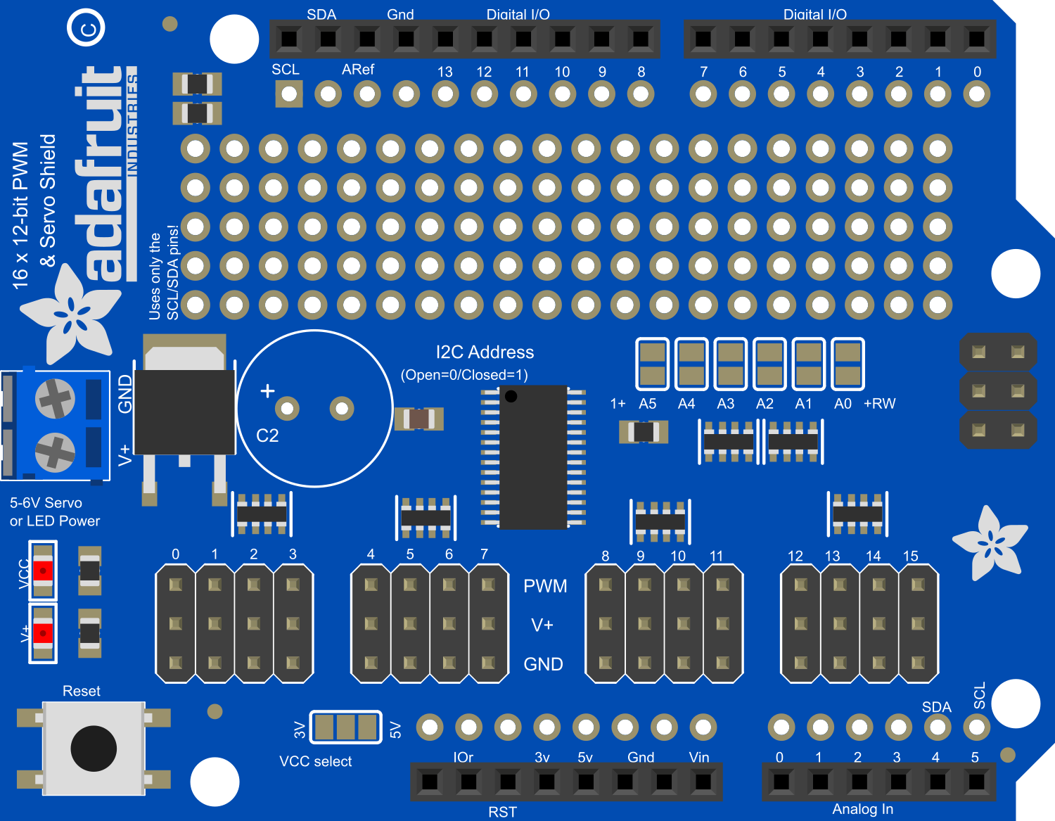
Pin Configuration and Descriptions

Pin Number Description
GND Ground
V+ Servo power supply (5-6V)
SCL I2C clock line
SDA I2C data line
A0-A5 Address jumpers for I2C address selection

Usage Instructions

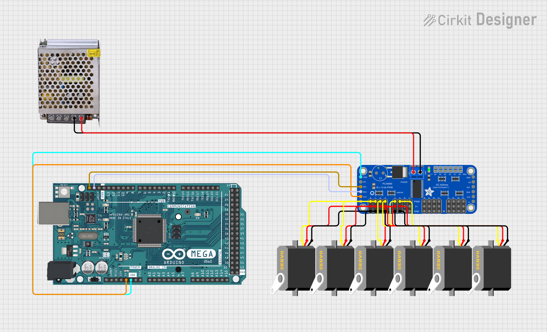
Connecting the Shield to Arduino

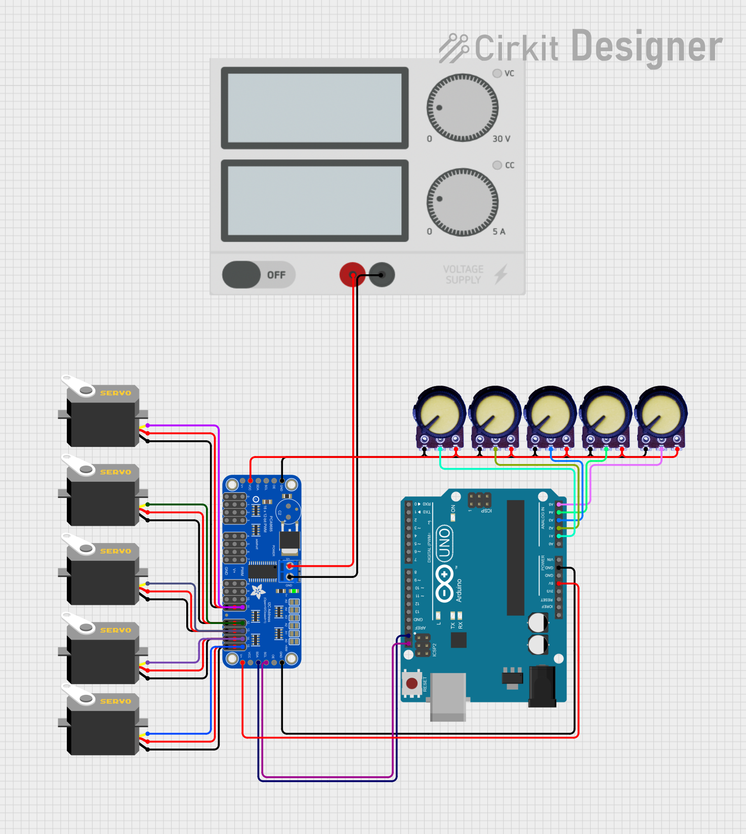
  1. Powering the Shield:

    • Ensure that the shield is powered correctly; you can use the Arduino's 5V pin or an external power supply for the servos.
    • Do not power high-torque servos directly from the Arduino's 5V pin.
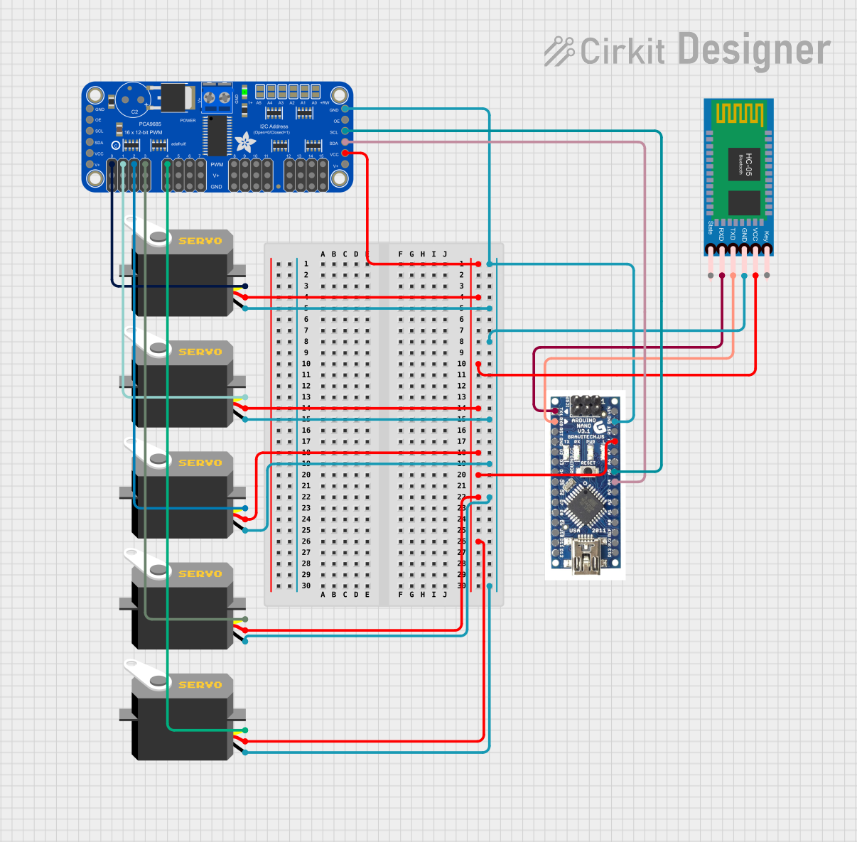
  2. I2C Communication:

    • Connect the SCL and SDA pins to the corresponding pins on the Arduino.
    • Use the A0-A5 jumpers to set the I2C address if multiple shields are used.
  3. Attaching Servos:

    • Connect your servos to the PWM output pins on the shield.
    • Ensure that the servos are correctly oriented; the signal wire should match the signal pin on the shield.

Programming the Shield

  • Use the Adafruit PWM Servo Driver Library to control the servos.
  • Initialize the library and set the PWM frequency to 50Hz, which is typical for servos.

Example Code for Arduino UNO

#include <Wire.h>
#include <Adafruit_PWMServoDriver.h>

// Initialize the PWM driver.
Adafruit_PWMServoDriver pwm = Adafruit_PWMServoDriver();

void setup() {
  pwm.begin();
  pwm.setPWMFreq(50);  // Set frequency to 50 Hz for servos
  Wire.setClock(400000); // Use 400kHz I2C frequency
}

void loop() {
  // Example: Turn servo on channel 0 to mid position
  uint16_t pulseLength = map(90, 0, 180, SERVOMIN, SERVOMAX);
  pwm.setPWM(0, 0, pulseLength);
  delay(1000);
  
  // Add code to control other servos as needed
}

Important Considerations and Best Practices

  • Always ensure that the power supply can handle the current draw of all servos combined.
  • Avoid disconnecting or connecting servos while the shield is powered to prevent damage.
  • Use capacitors to smooth out power supply fluctuations if necessary.

Troubleshooting and FAQs

Common Issues

  • Servos not responding: Check the power supply and I2C connections. Ensure that the correct I2C address is used.
  • Jittery servo movement: This can be due to insufficient power supply or noise in the signal. Check the power supply and consider using a capacitor.

Solutions and Tips

  • Power Supply: Use a dedicated power supply for the servos if they draw a lot of current.
  • I2C Addressing: Make sure the I2C address is unique if using multiple shields.
  • Library Usage: Always use the latest version of the Adafruit PWM Servo Driver Library for best compatibility.

FAQs

Q: Can I power the servos directly from the Arduino? A: It is not recommended to power high-torque servos directly from the Arduino due to the current limitations of the board.

Q: How do I change the I2C address? A: Solder the address jumpers A0-A5 on the shield to configure the I2C address.

Q: Can I use this shield with other microcontrollers besides Arduino? A: Yes, as long as the microcontroller supports I2C communication and you can provide the correct logic voltage.

Remember to always follow the best practices and safety guidelines when working with electronic components to ensure the longevity of your project and components.