Cirkit Designer Logo
Cirkit Designer
Your all-in-one circuit design IDE
Home / 
Component Documentation

How to Use XL6009E1 Boost Converter: Examples, Pinouts, and Specs

Image of XL6009E1 Boost Converter
Cirkit Designer LogoDesign with XL6009E1 Boost Converter in Cirkit Designer

Introduction

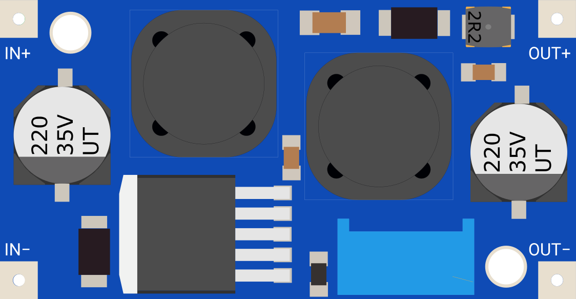
The XL6009E1 Boost Converter is a high-efficiency, adjustable DC-DC step-up voltage converter. It is designed to take a lower input voltage and boost it to a higher output voltage, making it ideal for applications where the power supply voltage is insufficient for the needs of the electronic system. Common applications include battery-powered devices, portable electronics, and systems requiring a stable voltage supply from a lower voltage source.

Explore Projects Built with XL6009E1 Boost Converter

Use Cirkit Designer to design, explore, and prototype these projects online. Some projects support real-time simulation. Click "Open Project" to start designing instantly!
Battery-Powered Boost Converter with USB Type-C and BMS
Image of Weird Case: A project utilizing XL6009E1 Boost Converter in a practical application
This circuit is a power management and conversion system that includes a boost converter, battery management system (BMS), and various MOSFETs and passive components. It is designed to regulate and boost the voltage from a 2000mAh battery, providing stable power output through a USB Type C interface. The circuit also includes protection and switching mechanisms to ensure safe and efficient power delivery.
Cirkit Designer LogoOpen Project in Cirkit Designer
Multi-Stage Voltage Regulation and Indicator LED Circuit
Image of Subramanyak_Power_Circuit: A project utilizing XL6009E1 Boost Converter in a practical application
This circuit is designed for power management, featuring buck and boost converters for voltage adjustment, and linear regulators for stable voltage output. It includes LEDs for status indication, and terminal blocks for external connections.
Cirkit Designer LogoOpen Project in Cirkit Designer
Battery-Powered DC Generator with XL4015 Buck Converter
Image of conveyor: A project utilizing XL6009E1 Boost Converter in a practical application
This circuit consists of a 12V battery connected to a rocker switch, which controls the input to an XL4015 DC Buck Step-down converter. The converter steps down the voltage to power a DC generator, with the generator's output connected back to the converter to form a feedback loop.
Cirkit Designer LogoOpen Project in Cirkit Designer
Voltage Regulation System with MT3608 Boost and LM2596 Buck Converters
Image of solar system router ups: A project utilizing XL6009E1 Boost Converter in a practical application
This circuit consists of two MT3608 boost converters and an LM2596 step-down module, each connected to separate 12V power supplies. The MT3608 modules are configured to step up the voltage from their respective power supplies, while the LM2596 module steps down the voltage from a 12V battery. Diodes are used to ensure correct current flow direction, potentially for protection or isolation between different parts of the circuit.
Cirkit Designer LogoOpen Project in Cirkit Designer

Explore Projects Built with XL6009E1 Boost Converter

Use Cirkit Designer to design, explore, and prototype these projects online. Some projects support real-time simulation. Click "Open Project" to start designing instantly!
Image of Weird Case: A project utilizing XL6009E1 Boost Converter in a practical application
Battery-Powered Boost Converter with USB Type-C and BMS
This circuit is a power management and conversion system that includes a boost converter, battery management system (BMS), and various MOSFETs and passive components. It is designed to regulate and boost the voltage from a 2000mAh battery, providing stable power output through a USB Type C interface. The circuit also includes protection and switching mechanisms to ensure safe and efficient power delivery.
Cirkit Designer LogoOpen Project in Cirkit Designer
Image of Subramanyak_Power_Circuit: A project utilizing XL6009E1 Boost Converter in a practical application
Multi-Stage Voltage Regulation and Indicator LED Circuit
This circuit is designed for power management, featuring buck and boost converters for voltage adjustment, and linear regulators for stable voltage output. It includes LEDs for status indication, and terminal blocks for external connections.
Cirkit Designer LogoOpen Project in Cirkit Designer
Image of conveyor: A project utilizing XL6009E1 Boost Converter in a practical application
Battery-Powered DC Generator with XL4015 Buck Converter
This circuit consists of a 12V battery connected to a rocker switch, which controls the input to an XL4015 DC Buck Step-down converter. The converter steps down the voltage to power a DC generator, with the generator's output connected back to the converter to form a feedback loop.
Cirkit Designer LogoOpen Project in Cirkit Designer
Image of solar system router ups: A project utilizing XL6009E1 Boost Converter in a practical application
Voltage Regulation System with MT3608 Boost and LM2596 Buck Converters
This circuit consists of two MT3608 boost converters and an LM2596 step-down module, each connected to separate 12V power supplies. The MT3608 modules are configured to step up the voltage from their respective power supplies, while the LM2596 module steps down the voltage from a 12V battery. Diodes are used to ensure correct current flow direction, potentially for protection or isolation between different parts of the circuit.
Cirkit Designer LogoOpen Project in Cirkit Designer

Technical Specifications

Key Technical Details

  • Model: XL6009E1
  • Function: DC-DC Step-up Boost Converter
  • Input Voltage Range: 3.0V to 32V
  • Output Voltage Range: 5V to 35V (Adjustable via potentiometer)
  • Output Current: Up to 4A (maximum)
  • Switching Frequency: 400kHz
  • Efficiency: Up to 94%
  • Operating Temperature: -40°C to +85°C

Pin Configuration and Descriptions

Pin Number Name Description
1 GND Ground connection for the input and output voltage.
2 VIN Input voltage to the converter.
3 VOUT Output voltage from the converter.
4 EN Enable pin for turning the converter on or off.

Usage Instructions

How to Use the Component in a Circuit

  1. Connecting Input Voltage: Connect the input voltage source to the VIN and GND pins. Ensure that the input voltage is within the specified range of 3.0V to 32V.

  2. Adjusting Output Voltage: Before connecting the load, use a multimeter to measure the output voltage while adjusting the onboard potentiometer until the desired voltage is reached.

  3. Connecting the Load: Connect the load to the VOUT and GND pins. Ensure that the load does not exceed the maximum output current rating of 4A.

  4. Enabling the Converter: If remote on/off control is required, connect the EN pin to a logic high level to enable the converter or to a logic low level to disable it.

Important Considerations and Best Practices

  • Always verify input and output voltages with a multimeter before connecting sensitive electronics.
  • Avoid exceeding the maximum input and output voltage and current ratings to prevent damage to the converter and connected devices.
  • Provide adequate cooling if the converter is expected to operate at high currents or in high-temperature environments.
  • Place a capacitor close to the input and output pins if the power supply or load has a high transient response to improve stability.

Troubleshooting and FAQs

Common Issues

  • Output voltage is too low or too high: Ensure the potentiometer is correctly adjusted. Check for proper functioning of the potentiometer.
  • Converter is not powering on: Verify that the input voltage is within the specified range and that the EN pin is set to a logic high level.
  • Excessive heat or noise: Check if the current draw is within the specified limit and ensure adequate cooling.

Solutions and Tips for Troubleshooting

  • If the output voltage cannot be adjusted, replace the potentiometer or check for any circuit faults.
  • Ensure that all connections are secure and that there are no short circuits.
  • If the device is overheating, reduce the load or improve ventilation and heat dissipation.

FAQs

Q: Can I use the XL6009E1 to charge batteries? A: Yes, but you must ensure that the output voltage is set correctly for the battery type and that additional charging circuitry is in place to safely manage the charging process.

Q: What is the maximum output voltage I can set? A: The maximum output voltage is 35V. Do not exceed this value.

Q: How do I enable or disable the converter remotely? A: You can control the EN pin using a microcontroller or switch. Apply a logic high level to enable and a logic low level to disable the converter.

Q: Is it possible to synchronize multiple XL6009E1 converters? A: The XL6009E1 does not have a synchronization feature, so running multiple converters in parallel requires careful consideration of phase and noise to prevent interference.

Example Code for Arduino UNO

Below is an example code snippet for controlling the EN pin of the XL6009E1 using an Arduino UNO. This code will enable the boost converter for 5 seconds and then disable it for 5 seconds in a loop.

const int enablePin = 7; // Connect to the EN pin of the XL6009E1

void setup() {
  pinMode(enablePin, OUTPUT);
}

void loop() {
  digitalWrite(enablePin, HIGH); // Enable the boost converter
  delay(5000);                   // Wait for 5 seconds

  digitalWrite(enablePin, LOW);  // Disable the boost converter
  delay(5000);                   // Wait for 5 seconds
}

Remember to adjust the enablePin to match the actual pin connected to the EN pin of the XL6009E1 on your Arduino UNO.