Cirkit Designer Logo
Cirkit Designer
Your all-in-one circuit design IDE
Home / 
Component Documentation

How to Use Adafruit 16x8 LED Matrix Backpack Pure Green: Examples, Pinouts, and Specs

Image of Adafruit 16x8 LED Matrix Backpack Pure Green
Cirkit Designer LogoDesign with Adafruit 16x8 LED Matrix Backpack Pure Green in Cirkit Designer

Introduction

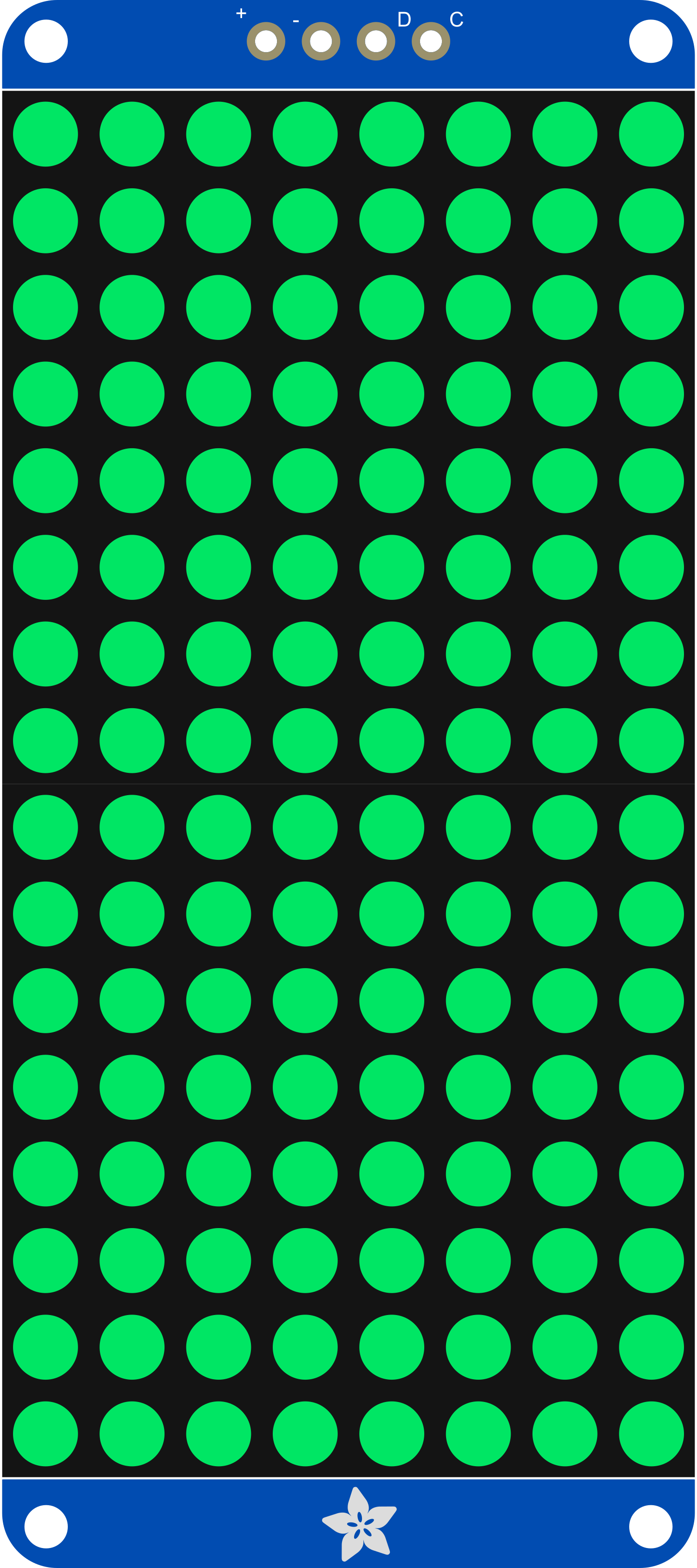
The Adafruit 16x8 LED Matrix Backpack Pure Green is a versatile and visually appealing display module designed for hobbyists and professionals alike. This LED matrix features 128 pure green LEDs arranged in a 16x8 grid, and it comes with an integrated backpack that simplifies connection to microcontrollers such as the Arduino UNO. Common applications include creating digital signage, displaying sensor data, creating simple games, or adding a visual interface to electronics projects.

Explore Projects Built with Adafruit 16x8 LED Matrix Backpack Pure Green

Use Cirkit Designer to design, explore, and prototype these projects online. Some projects support real-time simulation. Click "Open Project" to start designing instantly!
ESP32-Controlled Dual 8x8 LED Matrix Display with NTP Time Synchronization
Image of time: A project utilizing Adafruit 16x8 LED Matrix Backpack Pure Green in a practical application
This circuit features an ESP32 microcontroller connected to two cascaded 8x8 LED matrix displays, powered by a 3.3V battery. The ESP32 drives the displays to show time and other information, with the code indicating functionality for connecting to WiFi, synchronizing time via NTP, and displaying data on the matrices using custom fonts. Additionally, there is a separate 3.3V battery powering a red LED, which appears to function as a simple indicator light.
Cirkit Designer LogoOpen Project in Cirkit Designer
ESP32-Based Smart Weather Station with LED Display and Multiple Sensors
Image of Copy of Zegarek (1): A project utilizing Adafruit 16x8 LED Matrix Backpack Pure Green in a practical application
This circuit is a sensor and display system powered by an ESP32 microcontroller. It integrates multiple sensors (BH1750 light sensor, BMP280 pressure sensor, DS3231 RTC, and DS18B20 temperature sensor) and drives a series of MAX7219 8x8 LED matrices for visual output. The ESP32 communicates with the sensors via I2C and controls the LED matrices to display data.
Cirkit Designer LogoOpen Project in Cirkit Designer
ESP32-Based Smart Weather Station with LED Display and Multiple Sensors
Image of Copy of Zegarek: A project utilizing Adafruit 16x8 LED Matrix Backpack Pure Green in a practical application
This circuit is a multi-sensor data acquisition system using an ESP32 microcontroller. It integrates various sensors including a BH1750 light sensor, BMP280 pressure sensor, DS3231 RTC, and DS18B20 temperature sensor, and displays data on a series of MAX7219 8x8 LED matrices. The system is powered via USB and includes a green LED indicator.
Cirkit Designer LogoOpen Project in Cirkit Designer
Battery-Powered Smart Light with Proximity Sensor and OLED Display using Adafruit QT Py RP2040
Image of lab: A project utilizing Adafruit 16x8 LED Matrix Backpack Pure Green in a practical application
This circuit is a portable, battery-powered system featuring an Adafruit QT Py RP2040 microcontroller that interfaces with an OLED display, a proximity sensor, an accelerometer, and an RGB LED strip. The system is powered by a lithium-ion battery with a step-up boost converter to provide 5V for the LED strip, and it includes a toggle switch for power control. The microcontroller communicates with the sensors and display via I2C.
Cirkit Designer LogoOpen Project in Cirkit Designer

Explore Projects Built with Adafruit 16x8 LED Matrix Backpack Pure Green

Use Cirkit Designer to design, explore, and prototype these projects online. Some projects support real-time simulation. Click "Open Project" to start designing instantly!
Image of time: A project utilizing Adafruit 16x8 LED Matrix Backpack Pure Green in a practical application
ESP32-Controlled Dual 8x8 LED Matrix Display with NTP Time Synchronization
This circuit features an ESP32 microcontroller connected to two cascaded 8x8 LED matrix displays, powered by a 3.3V battery. The ESP32 drives the displays to show time and other information, with the code indicating functionality for connecting to WiFi, synchronizing time via NTP, and displaying data on the matrices using custom fonts. Additionally, there is a separate 3.3V battery powering a red LED, which appears to function as a simple indicator light.
Cirkit Designer LogoOpen Project in Cirkit Designer
Image of Copy of Zegarek (1): A project utilizing Adafruit 16x8 LED Matrix Backpack Pure Green in a practical application
ESP32-Based Smart Weather Station with LED Display and Multiple Sensors
This circuit is a sensor and display system powered by an ESP32 microcontroller. It integrates multiple sensors (BH1750 light sensor, BMP280 pressure sensor, DS3231 RTC, and DS18B20 temperature sensor) and drives a series of MAX7219 8x8 LED matrices for visual output. The ESP32 communicates with the sensors via I2C and controls the LED matrices to display data.
Cirkit Designer LogoOpen Project in Cirkit Designer
Image of Copy of Zegarek: A project utilizing Adafruit 16x8 LED Matrix Backpack Pure Green in a practical application
ESP32-Based Smart Weather Station with LED Display and Multiple Sensors
This circuit is a multi-sensor data acquisition system using an ESP32 microcontroller. It integrates various sensors including a BH1750 light sensor, BMP280 pressure sensor, DS3231 RTC, and DS18B20 temperature sensor, and displays data on a series of MAX7219 8x8 LED matrices. The system is powered via USB and includes a green LED indicator.
Cirkit Designer LogoOpen Project in Cirkit Designer
Image of lab: A project utilizing Adafruit 16x8 LED Matrix Backpack Pure Green in a practical application
Battery-Powered Smart Light with Proximity Sensor and OLED Display using Adafruit QT Py RP2040
This circuit is a portable, battery-powered system featuring an Adafruit QT Py RP2040 microcontroller that interfaces with an OLED display, a proximity sensor, an accelerometer, and an RGB LED strip. The system is powered by a lithium-ion battery with a step-up boost converter to provide 5V for the LED strip, and it includes a toggle switch for power control. The microcontroller communicates with the sensors and display via I2C.
Cirkit Designer LogoOpen Project in Cirkit Designer

Technical Specifications

Key Technical Details

  • Resolution: 16x8 (128 LEDs)
  • LED Color: Pure Green
  • Operating Voltage: 5V DC
  • Communication: I2C interface
  • I2C Addresses: 0x70 (default) - 0x77 (selectable with solder jumpers)
  • Dimensions: 1.2" x 3.0" (31mm x 76mm)

Pin Configuration and Descriptions

Pin Description
GND Ground connection
VCC Power supply (4.5V to 5.5V)
SDA I2C Data line
SCL I2C Clock line

Usage Instructions

Interfacing with a Microcontroller

  1. Power Connections: Connect the VCC pin to the 5V output on your microcontroller and the GND pin to a ground pin.
  2. I2C Connections: Connect the SDA and SCL pins to the corresponding I2C pins on your microcontroller. For an Arduino UNO, SDA is A4 and SCL is A5.
  3. Address Selection: If using multiple LED matrices, set unique I2C addresses using the solder jumpers on the back of the module.

Programming the Display

To control the LED matrix, you can use the Adafruit LED Backpack library available for Arduino. Here is a simple example to get started:

#include <Wire.h>
#include <Adafruit_GFX.h>
#include <Adafruit_LEDBackpack.h>

Adafruit_8x16matrix matrix = Adafruit_8x16matrix();

void setup() {
  matrix.begin(0x70); // Start the matrix with I2C address 0x70
  matrix.setBrightness(15); // Set brightness to a medium level (0-15)
}

void loop() {
  matrix.clear(); // Clear the matrix display
  matrix.setCursor(0, 0); // Set cursor at top-left corner
  matrix.print("Hello"); // Print "Hello" on the matrix
  matrix.writeDisplay(); // Update the display with the new data
  delay(2000); // Wait for 2 seconds
}

Important Considerations and Best Practices

  • Power Supply: Ensure that the power supply is within the specified range (4.5V to 5.5V).
  • Current Draw: Be mindful of the current draw when all LEDs are lit. If necessary, use an external power supply.
  • Brightness: Adjust the brightness to suit the ambient lighting conditions and to minimize power consumption.
  • I2C Pull-up Resistors: The module typically has built-in pull-up resistors for I2C. If multiple devices are on the bus, ensure that the total pull-up resistance is within acceptable limits.

Troubleshooting and FAQs

Common Issues

  • Display Not Lighting Up: Check the power connections and ensure the correct I2C address is used in the code.
  • Garbled Display: Verify that the I2C connections are secure and that there are no solder bridges on the address selection jumpers.
  • Dim Display: Increase the brightness setting in the code or check the power supply voltage.

Solutions and Tips for Troubleshooting

  • Power Issues: Use a multimeter to verify that the correct voltage is reaching the module.
  • I2C Communication: Use an I2C scanner sketch to confirm that the microcontroller is detecting the LED matrix.
  • Code Debugging: Add serial print statements in your code to debug logical errors or incorrect display outputs.

FAQs

Q: Can I daisy-chain multiple LED matrices? A: Yes, you can connect multiple matrices in series by connecting the SDA and SCL lines together and providing separate power if needed. Remember to set unique I2C addresses for each matrix.

Q: How do I display animations on the matrix? A: You can create animations by rapidly updating the display with different patterns. Use double buffering to prevent flicker: draw the next frame in the buffer while the current frame is displayed, then swap.

Q: What is the maximum brightness level for the LEDs? A: The maximum brightness level is 15. Be cautious with continuous use at maximum brightness as it may lead to higher power consumption and heat generation.

Q: How do I install the Adafruit LED Backpack library? A: You can install the library through the Arduino Library Manager by searching for "Adafruit LED Backpack" and installing it, or by downloading it from the Adafruit GitHub repository and manually installing it into your Arduino libraries folder.