How to Use DIALL 5 input: Examples, Pinouts, and Specs
Introduction
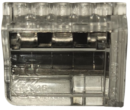
The WAGO 5 Input Module is a versatile terminal block designed for connecting up to five input signals in automation systems. Manufactured by WAGO, this module simplifies wiring and signal management, making it an essential component in industrial and building automation applications. Its compact design and reliable connections ensure efficient signal distribution and organization.
Explore Projects Built with DIALL 5 input

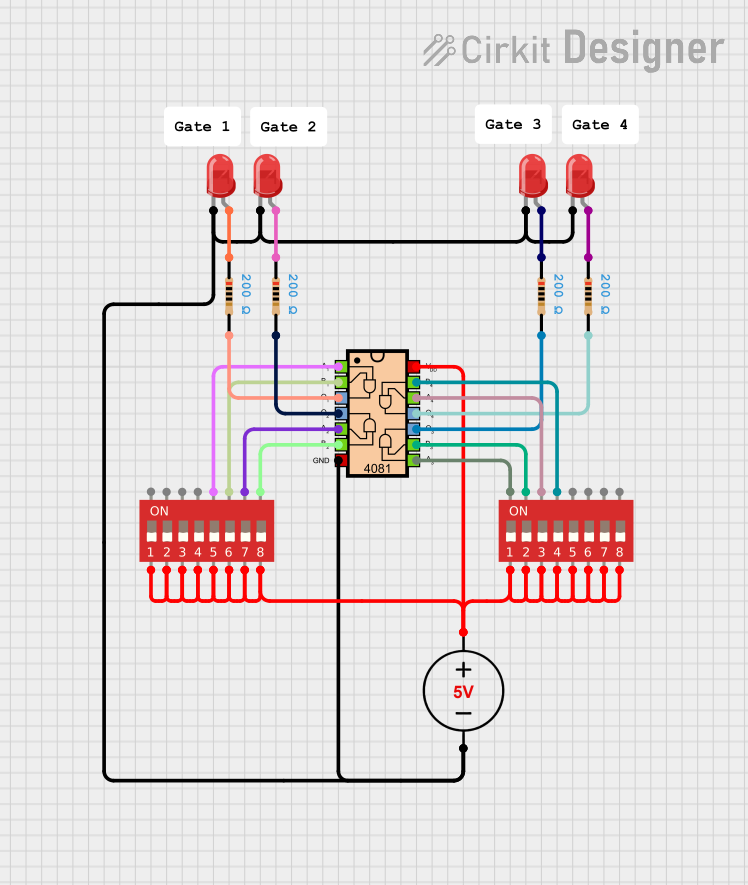


Explore Projects Built with DIALL 5 input
Common Applications and Use Cases
- Industrial automation systems for signal distribution
- Building automation for managing sensor inputs
- Control panels and PLC (Programmable Logic Controller) systems
- Signal management in machinery and equipment
- Simplifying wiring in complex electrical installations
Technical Specifications
The WAGO 5 Input Module is engineered for robust performance in demanding environments. Below are its key technical details:
General Specifications
| Parameter | Value |
|---|---|
| Manufacturer | WAGO |
| Number of Inputs | 5 |
| Rated Voltage | Up to 250 V |
| Rated Current | Up to 32 A |
| Wire Size Range | 28–12 AWG (0.08–4 mm²) |
| Operating Temperature | -20°C to +85°C |
| Mounting Type | DIN Rail |
| Housing Material | Polyamide (PA66) |
| Certifications | CE, UL, RoHS |
Pin Configuration and Descriptions
The WAGO 5 Input Module features five input terminals and a common ground terminal. Below is the pin configuration:
| Pin Number | Description | Notes |
|---|---|---|
| 1 | Input 1 | Connect the first input signal |
| 2 | Input 2 | Connect the second input signal |
| 3 | Input 3 | Connect the third input signal |
| 4 | Input 4 | Connect the fourth input signal |
| 5 | Input 5 | Connect the fifth input signal |
| GND | Common Ground | Shared ground for all inputs |
Usage Instructions
How to Use the WAGO 5 Input Module in a Circuit
- Mounting the Module: Secure the WAGO 5 Input Module onto a DIN rail in your control panel or enclosure.
- Wiring the Inputs:
- Strip the insulation from the wires to the appropriate length (refer to the wire size range in the specifications).
- Insert the stripped wire ends into the input terminals (1–5) and tighten the screws to secure the connections.
- Connecting the Ground:
- Connect the common ground wire to the GND terminal to ensure proper signal referencing.
- Verify Connections:
- Double-check all connections for proper placement and secure fastening.
- Ensure that the input signals do not exceed the rated voltage and current limits.
Important Considerations and Best Practices
- Signal Compatibility: Ensure that the input signals are within the rated voltage and current specifications of the module.
- Wire Preparation: Use appropriate wire sizes and strip lengths to ensure reliable connections.
- Environmental Conditions: Install the module in environments within the specified operating temperature range (-20°C to +85°C).
- Grounding: Proper grounding is essential for signal integrity and safety.
- Maintenance: Periodically inspect the connections for signs of wear or loosening.
Example: Connecting to an Arduino UNO
The WAGO 5 Input Module can be used to interface multiple input signals with an Arduino UNO. Below is an example of how to connect the module to an Arduino:
- Connect the input signals (e.g., sensors or switches) to the WAGO module's input terminals (1–5).
- Connect the GND terminal of the WAGO module to the GND pin of the Arduino UNO.
- Use jumper wires to connect the input terminals to the Arduino's digital input pins (e.g., D2–D6).
Sample Arduino Code
// Example code for reading inputs from the WAGO 5 Input Module
// connected to an Arduino UNO. Inputs are connected to pins D2–D6.

const int inputPins[5] = {2, 3, 4, 5, 6}; // Define input pins
int inputStates[5]; // Array to store input states

void setup() {
  // Initialize serial communication for debugging
  Serial.begin(9600);

  // Set input pins as INPUT
  for (int i = 0; i < 5; i++) {
    pinMode(inputPins[i], INPUT);
  }
}

void loop() {
  // Read the state of each input and print to the Serial Monitor
  for (int i = 0; i < 5; i++) {
    inputStates[i] = digitalRead(inputPins[i]); // Read input state
    Serial.print("Input ");
    Serial.print(i + 1);
    Serial.print(": ");
    Serial.println(inputStates[i]); // Print input state
  }

  delay(500); // Delay for readability
}
Troubleshooting and FAQs
Common Issues and Solutions
Loose Connections:
- Issue: Input signals are not being detected or are intermittent.
- Solution: Check all wire connections and ensure they are securely fastened in the terminals.
Signal Noise or Interference:
- Issue: Input signals are unstable or noisy.
- Solution: Use shielded cables for input signals and ensure proper grounding.
Exceeding Voltage/Current Ratings:
- Issue: The module is damaged or not functioning correctly.
- Solution: Verify that the input signals are within the rated voltage and current limits.
Incorrect Wiring:
- Issue: Inputs are not being read correctly by the connected device (e.g., Arduino).
- Solution: Double-check the wiring diagram and ensure that each input is connected to the correct terminal.
FAQs
Q1: Can the WAGO 5 Input Module handle analog signals?
A1: Yes, the module can handle analog signals as long as they are within the rated voltage and current specifications.
Q2: Is the module compatible with other microcontrollers besides Arduino?
A2: Yes, the module can be used with any microcontroller or PLC that supports the input signal types and voltage levels.
Q3: How do I clean the module?
A3: Use a dry or slightly damp cloth to clean the module. Avoid using harsh chemicals or solvents.
Q4: Can I use the module in outdoor environments?
A4: The module is not designed for direct exposure to outdoor conditions. Use it in a protected enclosure if outdoor use is required.