
How to Use Tower Pro MG995 DIGI HI-SPEED Servo Moto: Examples, Pinouts, and Specs
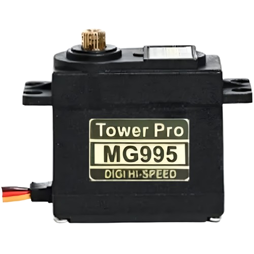
 Design with Tower Pro MG995 DIGI HI-SPEED Servo Moto in Cirkit Designer
Introduction
The Tower Pro MG995 DIGI HI-SPEED Servo Motor is a high-torque digital servo motor designed for applications requiring precise control and durability. Its metal gear train ensures long-lasting performance, even under high-stress conditions. This servo motor is widely used in robotics, remote-controlled (RC) vehicles, drones, and other hobbyist projects. With its fast response time and high torque output, the MG995 is ideal for tasks such as steering mechanisms, robotic arms, and pan-tilt camera systems.
Explore Projects Built with Tower Pro MG995 DIGI HI-SPEED Servo Moto
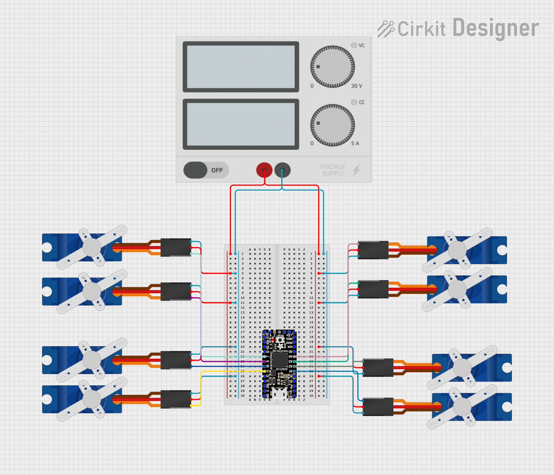 Open Project in Cirkit Designer
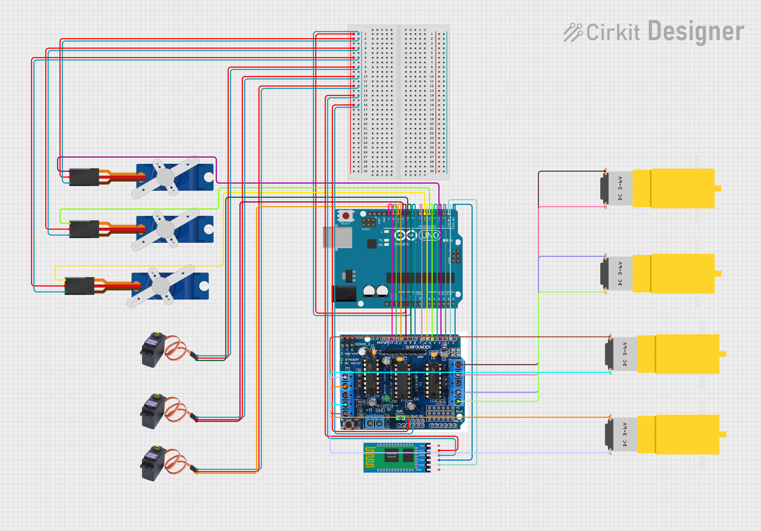 Open Project in Cirkit Designer
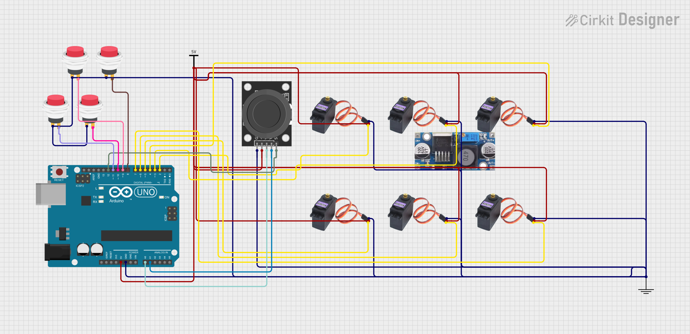 Open Project in Cirkit Designer
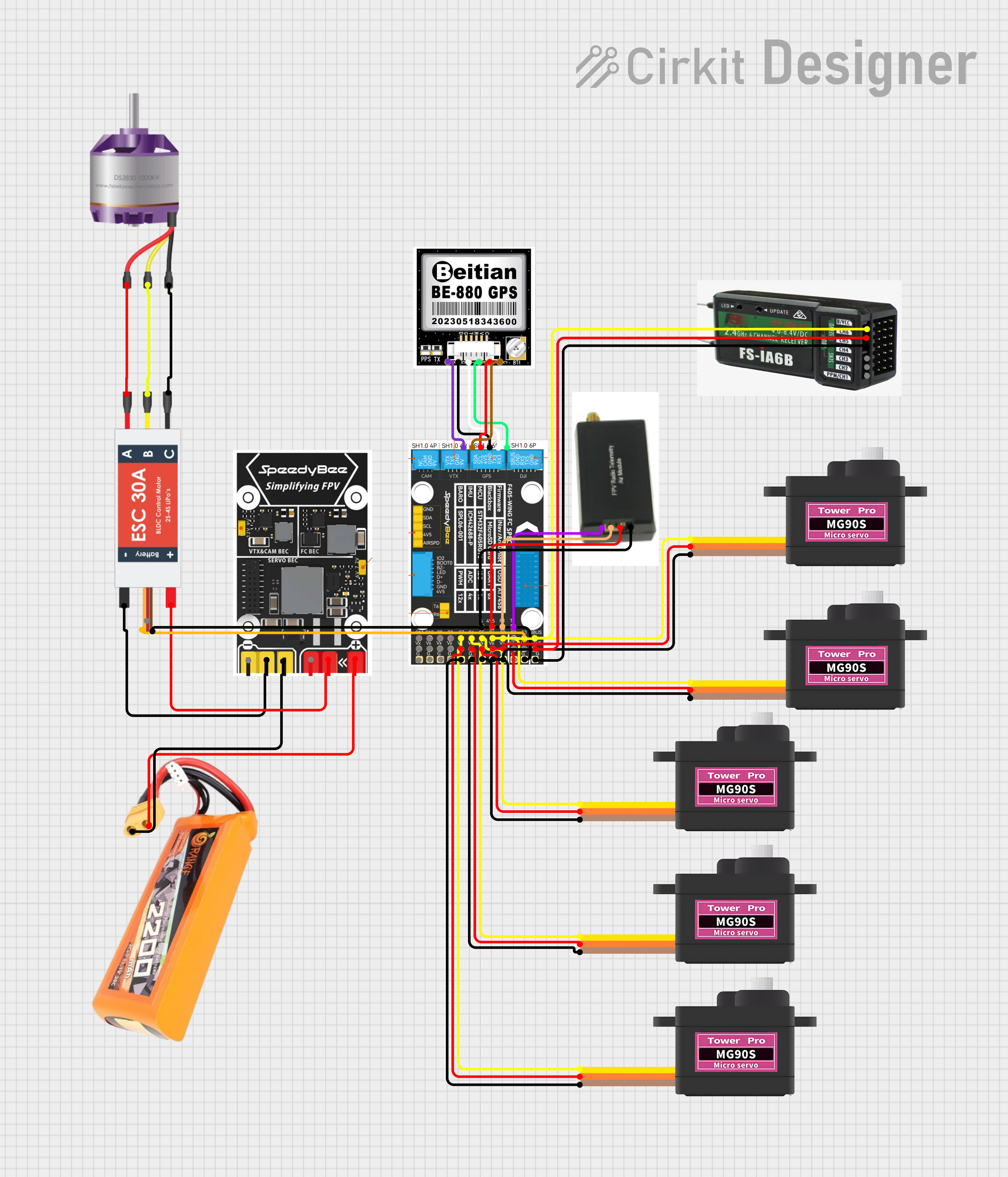 Open Project in Cirkit Designer
Explore Projects Built with Tower Pro MG995 DIGI HI-SPEED Servo Moto
Open Project in Cirkit DesignerOpen Project in Cirkit DesignerOpen Project in Cirkit DesignerOpen Project in Cirkit DesignerTechnical Specifications
Below are the key technical details of the Tower Pro MG995 Servo Motor:
| Specification | Value |
|---|---|
| Operating Voltage | 4.8V to 7.2V |
| Stall Torque | 9.4 kg·cm (4.8V), 11 kg·cm (6V) |
| Operating Speed | 0.20 sec/60° (4.8V), 0.16 sec/60° (6V) |
| Gear Type | Metal |
| Control Signal | PWM (Pulse Width Modulation) |
| PWM Pulse Range | 500 µs to 2500 µs |
| Weight | 55g |
| Dimensions | 40.7mm x 19.7mm x 42.9mm |
| Connector Type | 3-pin female header (Futaba style) |
Pin Configuration
The MG995 servo motor has a 3-pin connector with the following pinout:
| Pin | Wire Color | Description |
|---|---|---|
| 1 | Brown | Ground (GND) |
| 2 | Red | Power Supply (VCC) |
| 3 | Orange | Signal (PWM input) |
Usage Instructions
How to Use the MG995 Servo Motor in a Circuit
- Power Supply: Connect the red wire to a power source (4.8V to 7.2V). Ensure the power supply can provide sufficient current (at least 1.5A) to avoid performance issues.
- Ground Connection: Connect the brown wire to the ground (GND) of your circuit.
- Signal Input: Connect the orange wire to the PWM output pin of your microcontroller (e.g., Arduino, Raspberry Pi).
- PWM Signal: Use a PWM signal with a pulse width between 500 µs and 2500 µs to control the servo's position. A 1500 µs pulse typically sets the servo to its neutral position (90°).
Important Considerations and Best Practices
- Power Supply: Avoid powering the servo directly from the microcontroller's 5V pin, as it may not provide enough current. Use an external power source or a dedicated servo driver.
- Heat Management: Prolonged operation under high torque may cause the servo to heat up. Allow cooling periods to prevent damage.
- Signal Stability: Ensure the PWM signal is stable and free from noise to avoid erratic movements.
- Mechanical Limits: Do not force the servo beyond its physical rotation limits (typically 0° to 180°) to prevent gear damage.
Example Code for Arduino UNO
Below is an example of how to control the MG995 servo motor using an Arduino UNO:
#include <Servo.h> // Include the Servo library

Servo myServo; // Create a Servo object to control the MG995

void setup() {
  myServo.attach(9); // Attach the servo to pin 9 on the Arduino
}

void loop() {
  myServo.write(0); // Move the servo to 0 degrees
  delay(1000); // Wait for 1 second

  myServo.write(90); // Move the servo to 90 degrees (neutral position)
  delay(1000); // Wait for 1 second

  myServo.write(180); // Move the servo to 180 degrees
  delay(1000); // Wait for 1 second
}
Note: Ensure the servo is connected to an external power source if it draws more current than the Arduino can supply.
Troubleshooting and FAQs
Common Issues and Solutions
Servo Not Moving:
- Cause: Insufficient power supply.
- Solution: Use a power source capable of providing at least 1.5A.
Erratic Movements:
- Cause: Noisy or unstable PWM signal.
- Solution: Check the signal source and ensure proper grounding.
Overheating:
- Cause: Prolonged operation under high torque.
- Solution: Allow the servo to cool down periodically.
Limited Rotation:
- Cause: Servo is a standard (not continuous) type.
- Solution: The MG995 is designed for 0° to 180° rotation. Do not force it beyond this range.
FAQs
Q: Can the MG995 be used for continuous rotation?
- A: No, the MG995 is a standard servo designed for positional control within 0° to 180°. Modifications are required for continuous rotation.
Q: What is the maximum current draw of the MG995?
- A: The MG995 can draw up to 1.5A under stall conditions. Ensure your power supply can handle this.
Q: Can I control the MG995 with a Raspberry Pi?
- A: Yes, the MG995 can be controlled using the Raspberry Pi's GPIO pins with a PWM signal. However, use a level shifter if the signal voltage is below 5V.
Q: How do I calibrate the neutral position of the servo?
- A: Send a 1500 µs PWM pulse to the servo and adjust the mechanical linkage to align with the desired neutral position.
By following this documentation, you can effectively integrate the Tower Pro MG995 DIGI HI-SPEED Servo Motor into your projects.