How to Use ESP32-C3 Super Mini: Examples, Pinouts, and Specs
Introduction
The ESP32-C3 Super Mini, manufactured by Espressif Systems, is a compact, low-power microcontroller designed for IoT applications and embedded systems. It features integrated Wi-Fi and Bluetooth Low Energy (BLE) capabilities, making it an excellent choice for wireless communication in a wide range of projects. Its small form factor and energy efficiency make it ideal for battery-powered devices, smart home systems, wearables, and industrial automation.
Explore Projects Built with ESP32-C3 Super Mini


Explore Projects Built with ESP32-C3 Super Mini
Common Applications
- Internet of Things (IoT) devices
- Smart home automation
- Wearable electronics
- Wireless sensor networks
- Industrial control systems
- Low-power Bluetooth applications
Technical Specifications
The following table outlines the key technical specifications of the ESP32-C3 Super Mini:
| Specification | Details |
|---|---|
| Microcontroller Core | 32-bit RISC-V single-core processor |
| Clock Speed | Up to 160 MHz |
| Flash Memory | 4 MB (onboard) |
| SRAM | 400 KB |
| Wireless Connectivity | Wi-Fi 4 (802.11 b/g/n) and Bluetooth 5 (LE) |
| Operating Voltage | 3.0V to 3.6V |
| GPIO Pins | 15 (multiplexed for various functions) |
| Communication Interfaces | UART, SPI, I2C, I2S, PWM, ADC |
| ADC Resolution | 12-bit |
| Power Consumption | Ultra-low power in deep sleep mode (~5 µA) |
| Dimensions | 10 mm x 10 mm |
| Operating Temperature | -40°C to +85°C |
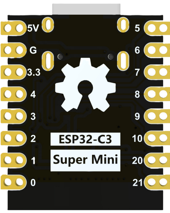
Pin Configuration and Descriptions
The ESP32-C3 Super Mini has a total of 15 GPIO pins, which are multiplexed for various functions. Below is the pinout description:
| Pin Number | Pin Name | Function | Description |
|---|---|---|---|
| 1 | GND | Ground | Connect to system ground. |
| 2 | 3V3 | Power Supply | 3.3V power input. |
| 3 | GPIO0 | GPIO, Boot Mode Select | General-purpose I/O, also used for boot mode. |
| 4 | GPIO1 | GPIO, UART TX | General-purpose I/O, UART transmit. |
| 5 | GPIO2 | GPIO, UART RX | General-purpose I/O, UART receive. |
| 6 | GPIO3 | GPIO, ADC Channel 1 | General-purpose I/O, ADC input. |
| 7 | GPIO4 | GPIO, PWM Output | General-purpose I/O, PWM signal output. |
| 8 | GPIO5 | GPIO, I2C SCL | General-purpose I/O, I2C clock line. |
| 9 | GPIO6 | GPIO, I2C SDA | General-purpose I/O, I2C data line. |
| 10 | GPIO7 | GPIO, SPI MOSI | General-purpose I/O, SPI data out. |
| 11 | GPIO8 | GPIO, SPI MISO | General-purpose I/O, SPI data in. |
| 12 | GPIO9 | GPIO, SPI SCK | General-purpose I/O, SPI clock. |
| 13 | GPIO10 | GPIO, SPI CS | General-purpose I/O, SPI chip select. |
| 14 | EN | Enable | Chip enable pin, active high. |
| 15 | RST | Reset | Reset pin, active low. |
Usage Instructions
How to Use the ESP32-C3 Super Mini in a Circuit
- Power Supply: Provide a stable 3.3V power supply to the
3V3pin and connect theGNDpin to the system ground. - Programming: Use the UART interface (GPIO1 for TX and GPIO2 for RX) to upload firmware. A USB-to-UART converter is typically required.
- Boot Mode: To enter bootloader mode for programming, hold the
GPIO0pin low while resetting the device. - GPIO Usage: Configure the GPIO pins as needed for digital I/O, ADC, PWM, or communication protocols (SPI, I2C, UART).
- Wireless Communication: Use the integrated Wi-Fi and Bluetooth features for wireless connectivity. Libraries such as
WiFiandBLEin the Arduino IDE can simplify development.
Important Considerations
- Voltage Levels: Ensure all connected peripherals operate at 3.3V logic levels to avoid damaging the ESP32-C3.
- Deep Sleep Mode: Use deep sleep mode to minimize power consumption in battery-powered applications.
- Antenna Placement: For optimal wireless performance, ensure the onboard antenna is not obstructed by metal or other conductive materials.
- Firmware: Use the latest Espressif SDK or Arduino core for ESP32 to access the full range of features.
Example Code for Arduino UNO
Below is an example of using the ESP32-C3 Super Mini to connect to a Wi-Fi network and print the IP address:
#include <WiFi.h> // Include the Wi-Fi library for ESP32

const char* ssid = "Your_SSID";       // Replace with your Wi-Fi network name
const char* password = "Your_Password"; // Replace with your Wi-Fi password

void setup() {
  Serial.begin(115200); // Initialize serial communication at 115200 baud
  delay(1000);          // Wait for the serial monitor to initialize

  Serial.println("Connecting to Wi-Fi...");
  WiFi.begin(ssid, password); // Start Wi-Fi connection

  while (WiFi.status() != WL_CONNECTED) {
    delay(500); // Wait until the connection is established
    Serial.print(".");
  }

  Serial.println("\nWi-Fi connected!");
  Serial.print("IP Address: ");
  Serial.println(WiFi.localIP()); // Print the device's IP address
}

void loop() {
  // Add your main code here
}
Troubleshooting and FAQs
Common Issues
Device Not Detected by Computer
- Ensure the USB-to-UART converter is properly connected.
- Verify that the correct COM port is selected in the Arduino IDE or other programming tools.
- Check if the
GPIO0pin is held low during reset for bootloader mode.
Wi-Fi Connection Fails
- Double-check the SSID and password for accuracy.
- Ensure the Wi-Fi network is within range and operational.
- Verify that the ESP32-C3 is not in deep sleep mode.
GPIO Pins Not Responding
- Confirm that the pins are not being used for other functions (e.g., SPI, I2C).
- Check for proper pull-up or pull-down resistors if required.
Solutions and Tips
- Use a multimeter to verify power supply voltage and continuity of connections.
- Update the ESP32-C3 firmware to the latest version for improved stability and features.
- Refer to the Espressif documentation for advanced debugging techniques and tools.
By following this documentation, you can effectively integrate the ESP32-C3 Super Mini into your projects and troubleshoot common issues with ease.